
Rifle scope and mount system

a technology of rifle scope and mount system, which is applied in the direction of weapons, weapon components, etc., can solve the problems of degrading the precision and accuracy of the firearm, correspondingly more massive, and shifting the telescope within the clamping ring

Inactive Publication Date: 2019-07-16
ASLIN JAMES DAVID +1
View PDF9 Cites 5 Cited by
  • Summary
  • Abstract
  • Description
  • Claims
  • Application Information

AI Technical Summary

Benefits of technology

The invention provides a way to attach a telescopic sight to a firearm in a way that prevents movement caused by impacts, recoil, and other factors. The scope can be positioned in a variety of ways, and the invention's built-in alignment system ensures that the sight is always properly aligned and can be easily and repeatably established in different locations within the mount system. This allows for precise targeting and improved accuracy when using the firearm with the attached scope.

Problems solved by technology

A recurring problem of the split-clamping ring portion of the mounting is the shifting of the telescope within the clamping ring due to the forces of inertia.
If the telescope shifts, the impact point on the target may also shift, degrading the precision and accuracy of the firearm which opposes the purpose of mounting the telescope which is the precision and reliability of projectile placement.
However, as interest in extreme long distance and precision shooting increases, modern telescopes are being produced with higher magnifications, which are of larger diameter to let in more light, and are correspondingly more massive.
Another problem encountered by users of firearm mounted telescopic sights encounter is the alignment of the telescope with the firearm's bore: at the time when a scope is mounted the rotational alignment of the scope about the scope's longitudinal axis is established, and once the scope is zeroed-in it is desirable that this alignment not be perturbed.
With traditional friction-type split-ring clamps, this desired alignment can be lost when tightening the clamping screws when installing the scope.
Traveling with scoped firearms presents additional challenges because many components inside the scope are delicate and rely on exceedingly precise adjustments and alignments of small and fine parts.
Like other parcels, rifles shipped by common carriers or aboard commercial passenger planes, buses, vessels, or trains are subjected to dropping, kicking, accidental shocks, and sometimes even willful abuse.
The consequence of “scope bite,” as this is called, can range from a minor blunt force inconvenience to a substantial injury including bleeding.

Method used


Image

  • Rifle scope and mount system
  • Rifle scope and mount system
  • Rifle scope and mount system

Examples


Embodiment Construction

[0038]While various aspects and features of certain embodiments have been summarized above, the following detailed description illustrates a few exemplary embodiments in further detail to enable one skilled in the art to practice such embodiments. The described examples are provided for illustrative purposes and are not intended to limit the scope of the invention.

[0039]In the following description, for the purposes of explanation, numerous specific details are set forth in order to provide a thorough understanding of the described embodiments. It will be apparent to one skilled in the art, however, that other embodiments of the present invention may be practiced without some of these specific details. Several embodiments are described herein, and while various features are ascribed to different embodiments, it should be appreciated that the features described with respect to one embodiment may be incorporated with other embodiments as well. By the same token, however, no single fea...


PUM


Abstract

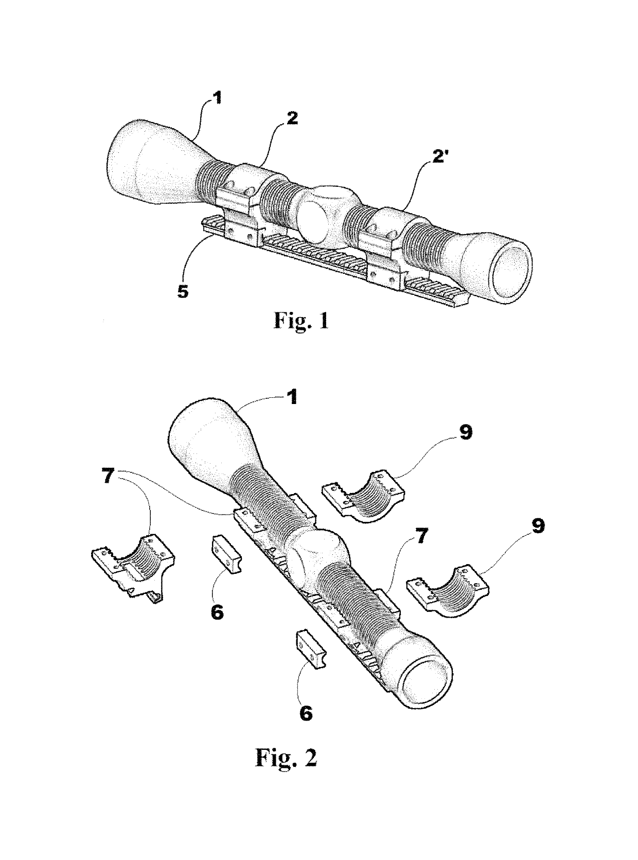
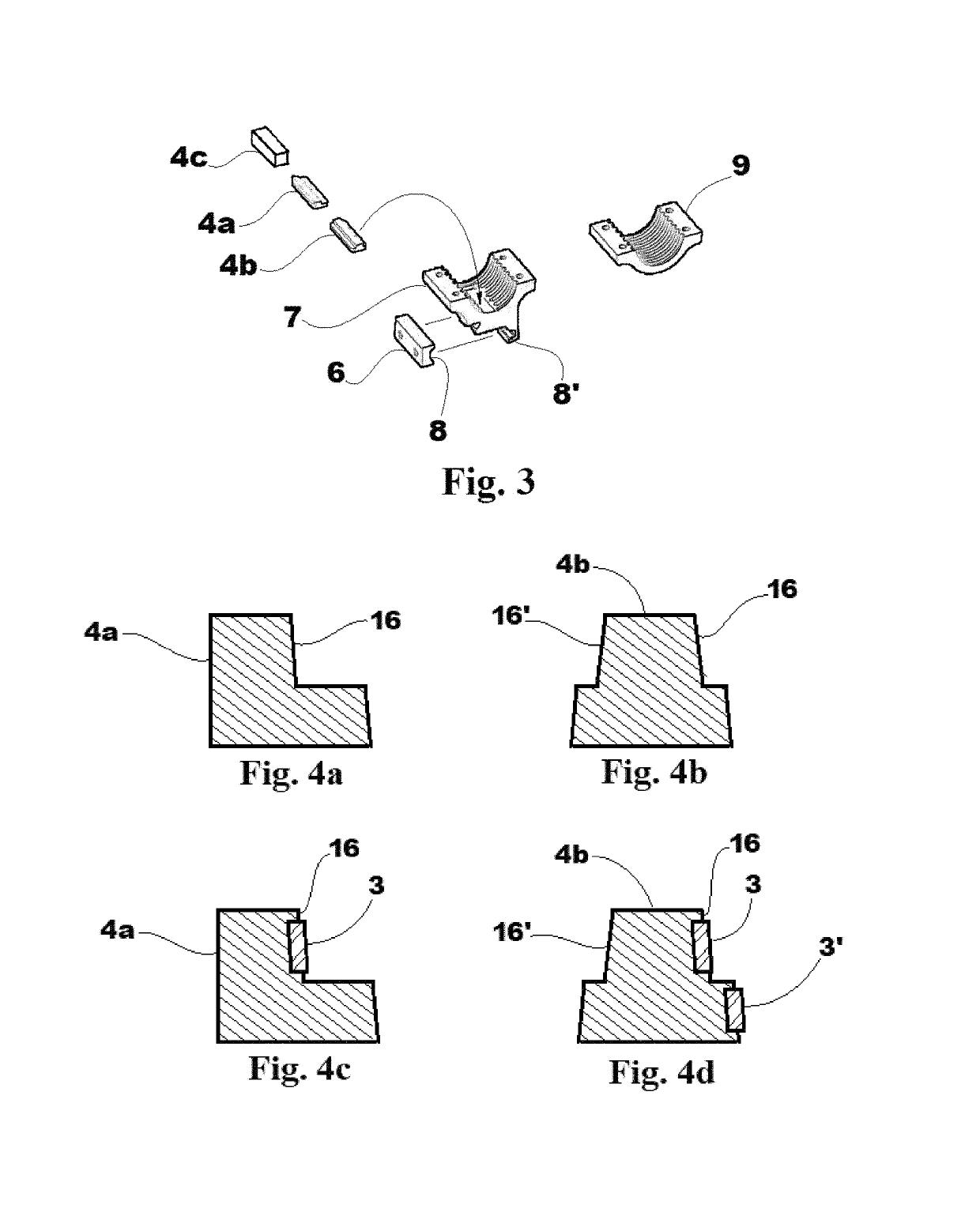
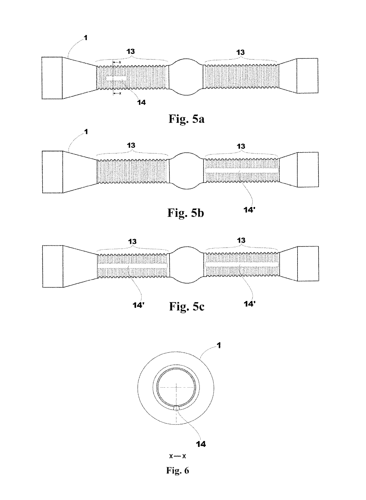
A scope and mount block assembly for a rifle includes a scope having sets of spaced apart ribs for seating into complementary arcuate grooves in scope mount components. An underside keyseat in the scope aligns with a complementary keyseat in a scope mount block, and a key residing in the combined volume of both keyseat enforces this alignment. The scope mount blocks clamp to any standard rail such as a Picatinny rail. When the scope is removed, leaving the blocks in place, it can be reattached so that the key reestablishes its alignment to the rifle and no re-sighting of the scope is required. Also, careful selection of pitches for the scope ribs and for spaced apart features for engagement of the mount blocks to a mounting rail can offer much finer incremental location of the scope on the rifle for more precise adjustment of eye relief.

Description

COPYRIGHT STATEMENT[0001]A portion of the disclosure of this patent document contains material that is subject to copyright protection. The copyright owner has no objection to the facsimile reproduction by anyone of the patent document or the patent disclosure as it appears in the Patent and Trademark Office patent file or records, but otherwise reserves all copyright rights whatsoever.CROSS-REFERENCE TO THE RELATED APPLICATION[0002]This application claims the benefit of priority to U.S. provisional patent application 62 / 669,512 “Rifle Scope and Mount Assembly” filed May 10, 2018. The entire content of U.S. provisional patent application 62 / 669,512 “Rifle Scope and Mount Assembly” filed May 10, 2018, is hereby incorporated into this document by reference.FIELD[0003]The invention relates to a rifle scope and means for securely attaching it to a rifle.BACKGROUND[0004]Rifle scopes, also called telescopic sights, were first invented and affixed to long barrel firearms around the late 18...

Claims


Application Information

Patent Timeline
IPC IPC(8): F41G11/00
CPCF41G11/001F41G11/003
Inventor ASLIN, JAMES DAVIDCRAPO, LARRY J
Owner ASLIN JAMES DAVID
Learn More