Image display apparatus

a technology of image display and display screen, which is applied in the field of image display screen, can solve the problems of unduly large apparatus as a whole, inability to present the observer with a high-quality image (virtual image), and inability to make the block satisfactorily slim, etc., and achieves the effect of high-quality images and sufficient long eye reli

Active Publication Date: 2006-02-21
MINOLTA CO LTD
View PDF16 Cites 4 Cited by
  • Summary
  • Abstract
  • Description
  • Claims
  • Application Information

AI Technical Summary

Benefits of technology

[0013]An object of the present invention is to provide an image display apparatus that is c

Problems solved by technology

However, a reflective liquid crystal panel needs to be illuminated from in front of its display surface, and therefore, unless a complicated arrangement is adopted in which the path of image light deviates greatly from that of illumination light, it is inevitable to dispose in front of the panel a combiner for combining the paths of image and illumination light.
However, in this arrangement, the beam diameter of the illumination light incident on the PBS block is so large that it is impossible to make the block satisfactorily slim.
Moreover, the con

Method used


Image

  • Image display apparatus
  • Image display apparatus
  • Image display apparatus

Examples


example 1

PRACTICAL EXAMPLE 1

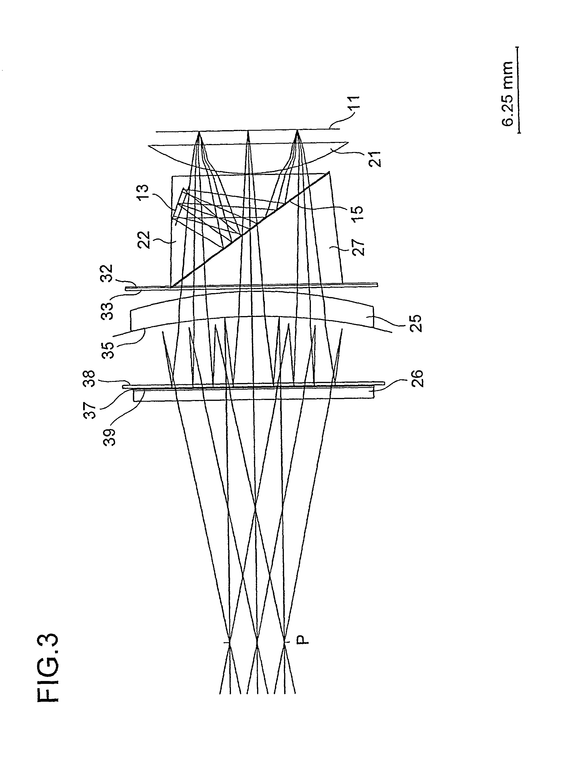
[0089]FIG. 3 shows the construction and optical path of a first practical example, and Table 1 shows the construction data thereof FIGS. 4 and 5 show the aberrations observed in this practical example. In the construction data, the surfaces are numbered in the order reverse to the direction in which the image light travels along its optical path. The refractive indices given are for light having a wavelength of 587.6 nm. These apply also to Tables 2 to 5 described later.

[0090]In this practical example, the focal length of the eyepiece optical system 12 as a whole is ft=18.000 mm, the focal length of the front portion 12a of the eyepiece optical system is fa=19.752 mm, the focal length of the rear portion 12b of the eyepiece optical system is fb=27.948 mm, and the distance from the rear end of the eyepiece optical system to the exit pupil is Epd=19.296 mm. Hence, fa / ft=1.097, and Epd / fb=0.690. The angle between the optical axis of the eyepiece optical system and a ...

example 2

PRACTICAL EXAMPLE 2

[0091]FIG. 6 shows the construction and optical path of a second practical example, and Table 2 shows the construction data thereof FIGS. 7 and 8 show the aberrations observed in this practical example.

[0092]In this practical example, ft=18.000 mm, fa=19.234 mm, fb=38.912 mm, Epd=26.809 mm, fa / ft=1.069, Epd / fb=0.689, and θ=35°. The prisms 22 and 27 are omitted.

[0093]The meniscus lens 25 has its convex surface (surface 11) formed as an aspherical surface, which is defined by expression (3) below.

Z=C·h2 / {1+[1−(1+K)·C2·h2]1 / 2 }+A4·h4+A6·h6+A8·h8+A10·h10  (3)

where Z represents the displacement along the optical axis Ax, C represents the curvature (the reciprocal of the radius of curvature), h represents the distance from the optical axis, K represents a conic constant, and A4 to A10 represent the coefficients for the terms of orders 4 to 10.

[0094]The aspherical surface of the meniscus lens 25 has the following coefficients: K=0, A4=−0.962037×10⁻⁴, A6=0.275900×10⁻⁵, A8...

example 3

PRACTICAL EXAMPLE 3

[0095]FIG. 9 shows the construction and optical path of a third practical example, and Table 3 shows the construction data thereof FIGS. 10 and 11 show the aberrations observed in this practical example.

[0096]In this practical example, ft=18.000 mm, fa=18.804 mm, fb=38.123 mm, Epd=14.818 mm, fa / ft=1.045, Epd / fb=0.389, and θ=35°. The prisms 22 and 27 are omitted.

[0097]The meniscus lens 25 is composed of a concave surface side portion 25a made of glass and a convex surface side portion 25b made of resin, and has its convex surface (surface 12) formed as an aspherical surface. This aspherical surface has the following coefficients: K=0, A4=0.147835×10⁻³, A6=0.811462×10⁻⁶, A8=−0.127597×10⁻⁷, A10=0.767565×10⁻¹⁰.

[0098]Moreover, the planoconvex lens 26 has its observation point P side surface (surface 1) formed as an aspherical surface. This aspherical surface has the following coefficients: K=0, A4=0.331917×10⁻⁴, A6=−0.159489×10⁻⁵, A8=0.188617×10⁻⁷, A10=−0.770228×10⁻¹⁰....


PUM


Abstract

An image display apparatus forms illumination light from a light source into image light by using a reflective display device, and directs the image light through an eyepiece optical system to an eye to present a virtual image of the image carried by the image light. To realize an image display apparatus of this type that is compact, affords a sufficiently long eye relief, and offers wide-field, high-quality images, a combiner for making the optical path of the illumination light from the light source overlap with that of the image light is disposed inside the eyepiece optical system, a positive lens is provided in the rear potion of the eyepiece optical system between the display device and the combiner, a concave reflective surface is provided in the front portion of the eyepiece optical system between the combiner and the observation point, and the eyepiece optical system is designed to be overtelecentric as a whole.

Description

[0001]This application is based on Japanese Patent Application No. 2000-293975 filed on Sep. 27, 2000, the contents of which are hereby incorporated by reference.BACKGROUND OF THE INVENTION[0002]1. Field of the Invention[0003]The present invention relates to an image display apparatus that is used in front of an eye, such as those used as viewfinders in various cameras and as head-mounted displays.[0004]2. Description of the Prior Art[0005]Many video cameras and digital cameras are equipped with an image display apparatus as a viewfinder. On the other hand, image display apparatus of the type called head-mounted displays (HMDs) have been becoming increasingly popular in recent years. These image display apparatus are used in front of an eye, and are typically composed of a display device for displaying an image, a light source for feeding illumination light to the display device, and an eyepiece optical system for directing image light (the light carrying the image) from the display...

Claims


Application Information

Patent Timeline
IPC IPC(8): G02B27/14G02B17/08G02B25/00G02B27/01G02B27/02G02B27/28G02F1/13G02F1/1335
CPCG02B27/0172
Inventor KOBAYASHI, YASUSHIOHZAWA, SOH
Owner MINOLTA CO LTD
Why Eureka
Try Eureka