Toner and method for producing the same, and image-forming method using the same

a technology of toner and image, applied in the field of toner, can solve the problems of insufficient satisfaction of recent demands of conventional dry toners, inability to efficiently produce high-quality images, and limited miniaturization of dry toners which are crushed and classified, etc., and achieves high image density, high resolution, and high quality.

Active Publication Date: 2006-03-30
RICOH KK
View PDF20 Cites 91 Cited by
  • Summary
  • Abstract
  • Description
  • Claims
  • Application Information

AI Technical Summary

Benefits of technology

[0022] The toner of the present invention can be contained in a developer. When image formation is performed by using such a developer, there can be formed high quality images with high image density and high resolution.
[0023] The toner of the present invention can be commercialized as a toner container in which the toner of the present invention is loaded. When image formation is performed by using the toner of the present invention loaded in the toner container, there can be formed high quality images with high image density and high resolution.
[0024] The toner of the present invention can be loaded in a process cartridge. Such a process cartridge comprises a latent electrostatic image bearing member and a developing unit which develop a latent electrostatic image formed on the latent electrostatic image bearing member with the toner of the present invention so as to form a visible image. This process cartridge is detachable to an image-forming apparatus and excels in easy handling or convenience. Since the process cartridge comprises the toner of the present invention, the process cartridge is capable of forming high quality images with high image density and high resolution.
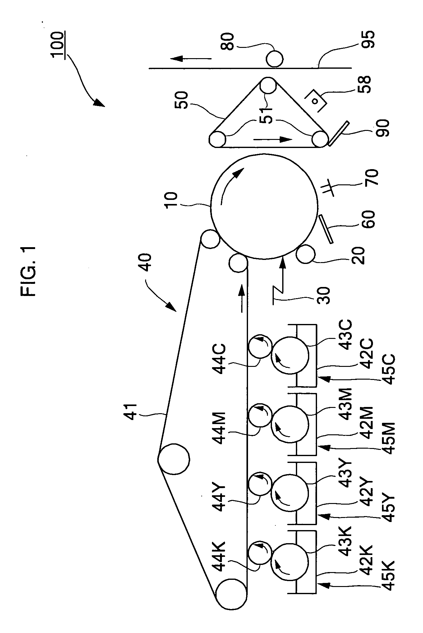
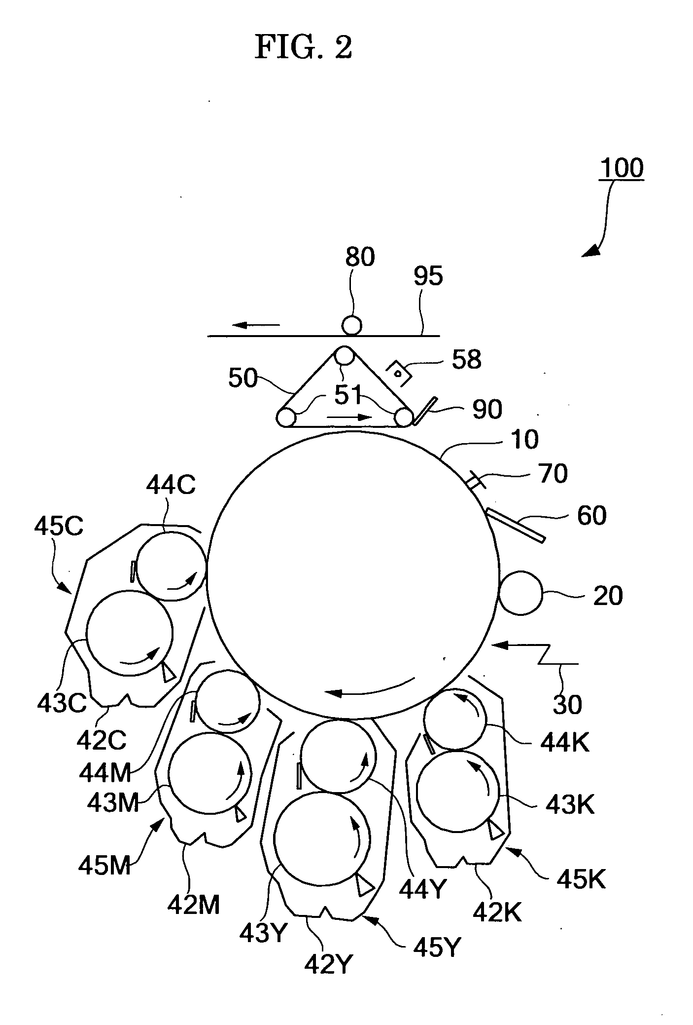
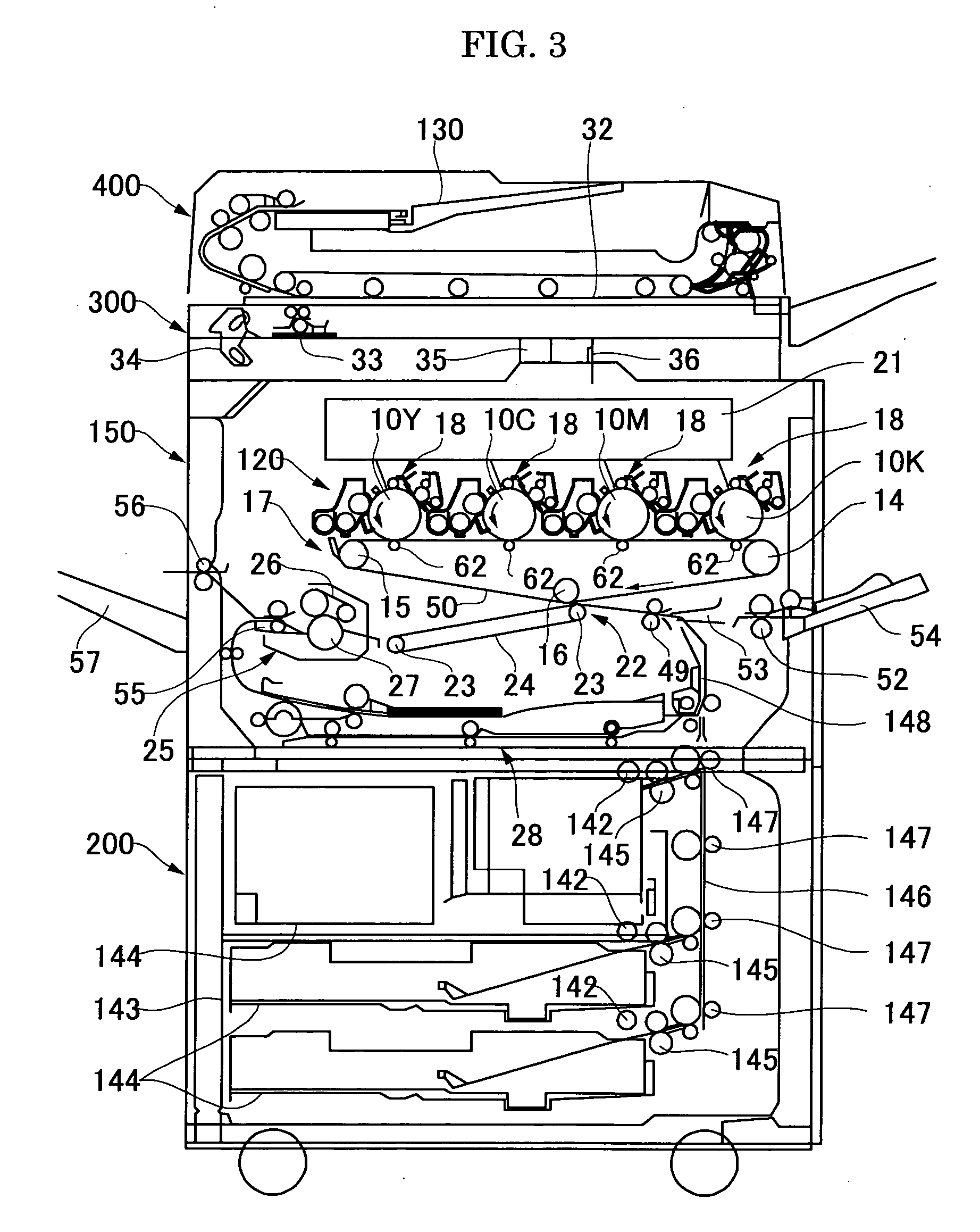
[0025] The toner of the present invention can be loaded in an image-forming apparatus. Such an image-forming apparatus comprises a latent electrostatic image bearing member, a latent electrostatic image forming unit which configured to form a latent electrostatic image on the latent electrostatic image bearing member, a developing unit which is configured to develop the latent electrostatic image with the toner of the present invention so as to form a visible image, a transferring unit which is configured to transfer the visible image to a recording medium, and a fixing unit which is configured to fix the transferred image onto the recording medium. In course of image formation by means of the image-forming apparatus, the latent electrostatic image is developed with the toner of the present invention by the developing unit, the visible image is transferred to a recording medium by the transferring unit, and the transferred image is fixed onto the recording medium by the fixing unit. As a result, there are formed high quality images with high image density and high resolution.
[0026] The image-forming method of the present invention comprising: forming a latent electrostatic image on a latent electrostatic image bearing member; developing the latent electrostatic image bearing member with the toner of the present invention so as to make the latent electrostatic image visible; transferring the visible image to a recording medium; and fixing the transferred image onto the recording medium. In the image-forming method of the present invention, a latent electrostatic image is formed on a latent electrostatic image bearing member, the latent electrostatic image is developed with the toner of the present invention so as to make the latent electrostatic image visible, the visible image is transferred to a recording medium, and the transferred image is fixed onto the recording medium. As a result, a high quality image with high image density and high resolution is formed under the conditions for low-temperature fixing.

Problems solved by technology

The conventional dry toners, however, cannot sufficiently satisfy the recent demands such as of high quality, formation of high quality image, and low-temperature fixing properties.
Specifically, the dry toners which are crushed and classified have limits in miniaturization of the toner, or crushing yields.
Therefore, there is a problem such that a toner having small particle size and sharp particle size distribution, and is capable of forming high quality images cannot be efficiently produced.
These attachments are liable to decrease charging ability, and thus adversely affect on a resistance of the toner to the environmental changes.
When this washing method is applied to the elongation toner, the ionic impurities or surfactant may be merely removed from the toner particles, but the charging ability is not sufficiently maintained.
As described above, the current situations are such that there have not yet provided a toner having excellent charging ability, shelf stability, low-temperature fixing properties and high quality image formation, a method for producing such a toner, and relative technologies utilizing such a toner.

Method used


Image

  • Toner and method for producing the same, and image-forming method using the same
  • Toner and method for producing the same, and image-forming method using the same
  • Toner and method for producing the same, and image-forming method using the same

Examples


synthesis example 1

Synthesis of Crystalline Polyester 1

[0429] Into a 5 liter four necked flask equipped with a nitrogen gas feed tube, a dewatering tube, a stirrer and a thermocouple, were poured 2,070 g of 1,4-butane diol, 2,535 g of fumaric acid, 291 g of trimellitic anhydride, and 4.9 g of hydroquinone, and the mixture was allowed to react at 160° C. for 5 hours, at 200° C. for 1 hour, and at 8.3 kPa for 1 hours, to thereby yield Crystalline Polyester 1.

[0430] The thus obtained Crystalline Polyester 1 had a melting point of 128° C., DSC endothermic peak temperature of 130° C., a number average molecular mass (Mn) of 900, mass average molecular mass (Mw) of 3,500, and a ratio Mw / Mn of 3.89. Note that Mn and Mw were obtained in terms of a molecular mass distribution of a tetrahydrofuran (THF) soluble part measured by means of gel permeation chromatography (GPC). The infrared spectrograph of the Crystalline Polyester 1 had an absorption band based on 6 CH (out-of-plane deformation vibration) of ole...

synthesis examples 2-6

Synthesis of Crystalline Polyesters 2-6

[0431] Crystalline Polyesters 2-6 of Synthesis Examples 2-6 were synthesized in the same manner as Synthesis Example 1, provided that the usage amount of the acid components were changed as in Table 1. The properties of the thus obtained crystalline polyesters are summarized in Table 1.

TABLE 1acid component (g)DCSynthesistrimelliticTm.emodothermicδCHExamplefumaric acidmaleic acidanhydrate(° C.)MwMnMw / Mn(cm−1)122822542911281303,5009003.899702253502911391402,8008003.50968320285082911131193,3007004.7197041775762291941001,5008001.8897051775762582919911,9002,4004.9699961268126858255539,7353,4252.84961

production example 1

Preparation of Crystalline Polyester Dispersion 1

[0432] Into 2 L metal contained were poured 100 g of Crystalline Polyester 4 of Synthesis Example 4 and 400 g of ethyl acetate, and the mixture was dissolved by heating at 79° C. (Tm) and then cooled in iced water. The resultant was added with 500 ml of glass beads having a diameter of 3 mm and crashed by means of Batch-type Sand Mill (manufactured by Kanpe Hapio Co., Ltd.) for 10 hours, and ethyl acetate was partially removed to thereby Crystalline Polyester Dispersion 1 having an volume average particle diameter (Dv) of 0.4 μm, and a solid content of 50%.


PUM

PropertyMeasurementUnit
acid valueaaaaaaaaaa
pHaaaaaaaaaa
conductivityaaaaaaaaaa

Abstract

There are provided: a method for producing a toner containing to granulate a toner and to subjecting the granulated toner to at least washing with an alkali washing solution, in which the total organic carbon amount extractable from the alkali-washed toner is 200 ppm/g or less; a toner comprising polyester in which the total organic carbon amount extractable from the toner is 200 ppm/g or less, under the condition that the toner is subjected to washing with the alkali washing solution before extracting; and an image-forming method using such a toner.

Description

BACKGROUND OF THE INVENTION [0001] 1. Field of the Invention [0002] The present invention relates to a toner which is suitably applicable for an electrophotography, a latent electrostatic recording method, a latent electrostatic printing method and the like. The present invention also relates to an efficient method for producing such a toner. Moreover, the present invention is directed to a developer, a toner container, a process cartridge, an image-forming apparatus, and an image-forming method, all of which employ the aforementioned toner. [0003] 2. Description of the Related Art [0004] Dry toners have been conventionally applied in electrophotography, latent electrostatic recording methods, latent electrostatic printing methods, and the like. The dry toners in use are generally obtained by kneading a toner binder such as styrene resin, acrylic resin, polyester resin or the like together with other component such as a colorant, and crushing the mixture. [0005] The conventional dry...

Claims


Application Information

Patent Timeline
Patent Type & Authority Applications(United States)
IPC IPC(8): G03G9/087
CPCG03G9/0804G03G9/09725G03G9/0815G03G9/0819G03G9/0821G03G9/08702G03G9/08753G03G9/08755G03G9/08764G03G9/08791G03G9/08795G03G9/08797G03G9/09708G03G9/09716G03G9/0806
Inventor YAMASHITA, HIROSHITANAKA, CHIAKIWATANABE, YOHICHIROHSUGIYAMA, TSUNEMIOHKI, MASAHIROMATSUOKA, SONOHYAMADA, MASAHIDEWATANABE, NAOHIROSAITOH, AKINORIINOUE, RYOTA
Owner RICOH KK
Why Eureka
Try Eureka