Image Processing Apparatus, Image Apparatus, Image Processing Method, and Computer Program

a technology of image processing and image processing method, applied in the field of image processing apparatus, imaging apparatus, image processing method, and computer program, can solve the problems of low image quality, deterioration of signal-to-noise ratio (s/n), and limited amount of electric charge that can be accumulated in photoelectric conversion elements, etc., to achieve high-quality natural-looking output image and wide dynamic range

Active Publication Date: 2008-09-11
SONY SEMICON SOLUTIONS CORP
View PDF22 Cites 98 Cited by
  • Summary
  • Abstract
  • Description
  • Claims
  • Application Information

AI Technical Summary

Benefits of technology

[0014]It is also desirable to provide an image processing apparatus, an imaging apparatus, an image processing method, and a computer program that are adapted to perform image processing on two types of input images, that is, a long-time exposure image and a short-time exposure image, in which a pixel whose brightness level or the like changes due to movement or the like of a subject is detected and is subjected to restrictive processing to prevent grayscale error or false color of the pixel to generate a high-quality image.
[0045]According to an embodiment of the present invention, therefore, a long-time exposure image and a short-time exposure image are input, and a wide dynamic range image is generated by selectively combining effective pixel values in the long-time and short-time exposure images. In this process, a brightness-change pixel in which it is determined that a brightness change has occurred during a photographic period corresponding to a long-time exposure time is detected, and the pixel value of the detected brightness-change pixel is replaced to perform an image correction process. Specifically, a blurred image is generated on the basis of the wide dynamic range image, and a pixel value of an output image is determined using a pixel value in each of the generated blurred image and the wide dynamic range image, which is associated with the pixel position of the brightness-change pixel. This can prevent the occurrence of grayscale error or false color of the brightness-change pixel due to movement or the like of a subject, resulting in a high-quality natural-looking output image.

Problems solved by technology

However, there is a limit to the amount of electric charge that can be accumulated in photoelectric conversion elements.
That is, a “white-out” problem occurs.
In the photography of a subject including both bright and dark areas, however, high-speed shutter release does not ensure sufficient exposure time in the dark areas, resulting in deterioration of signal-to-noise (S / N) ratio and low image quality.
Further, while a significantly wide dynamic range is achieved by a logarithmic response, a logarithmic response circuit is susceptible to threshold variations or the like of the transfer transistor 102.

Method used


Image

  • Image Processing Apparatus, Image Apparatus, Image Processing Method, and Computer Program
  • Image Processing Apparatus, Image Apparatus, Image Processing Method, and Computer Program
  • Image Processing Apparatus, Image Apparatus, Image Processing Method, and Computer Program

Examples


first embodiment

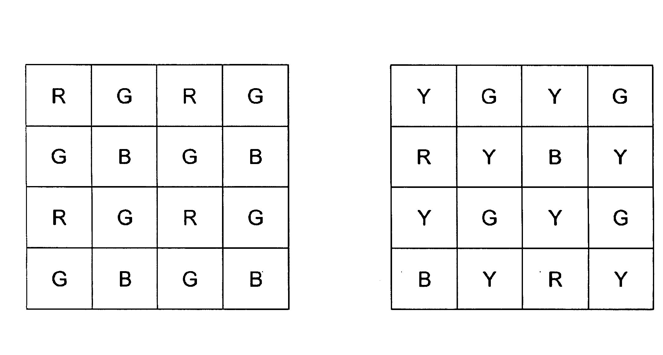
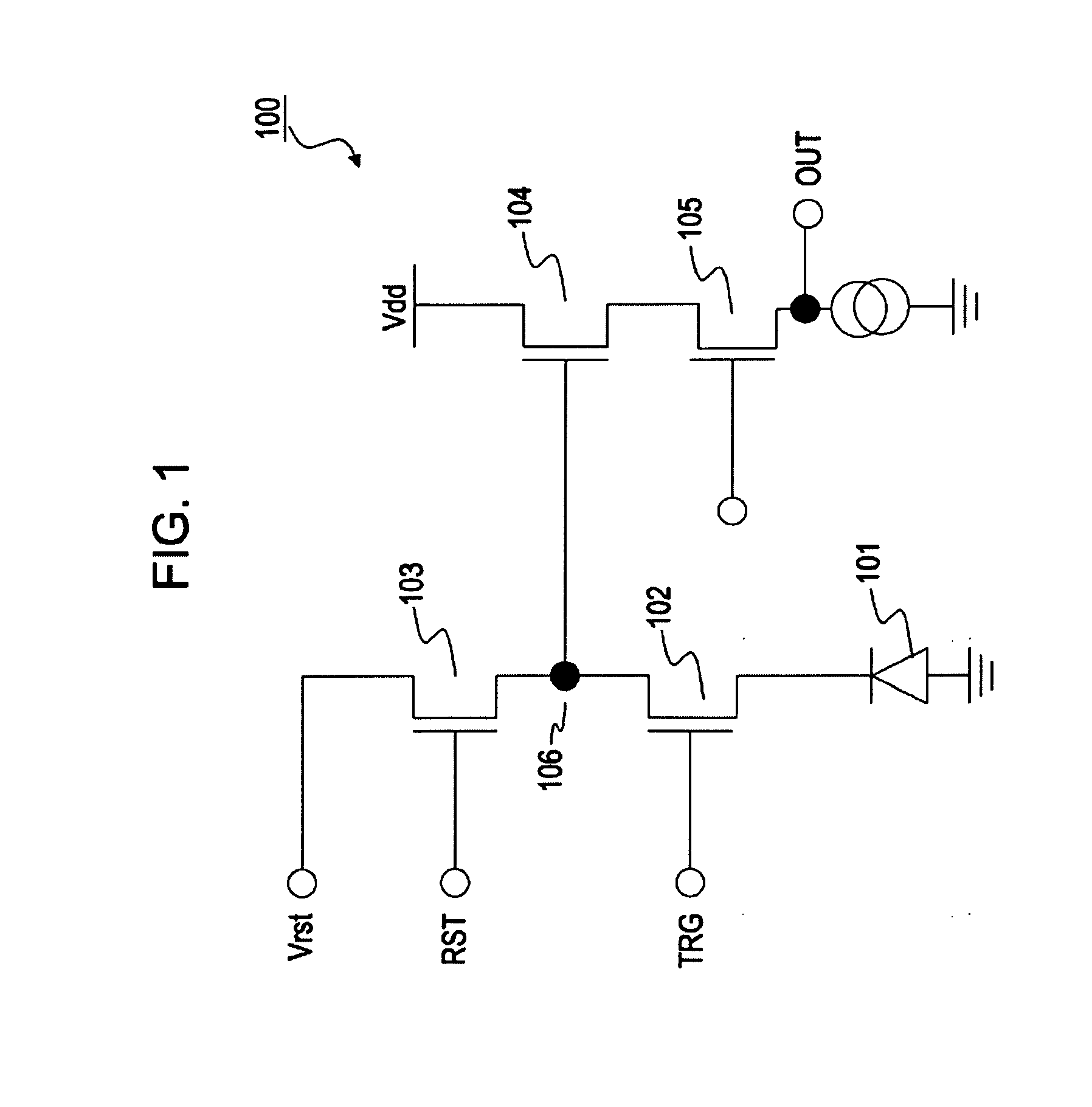
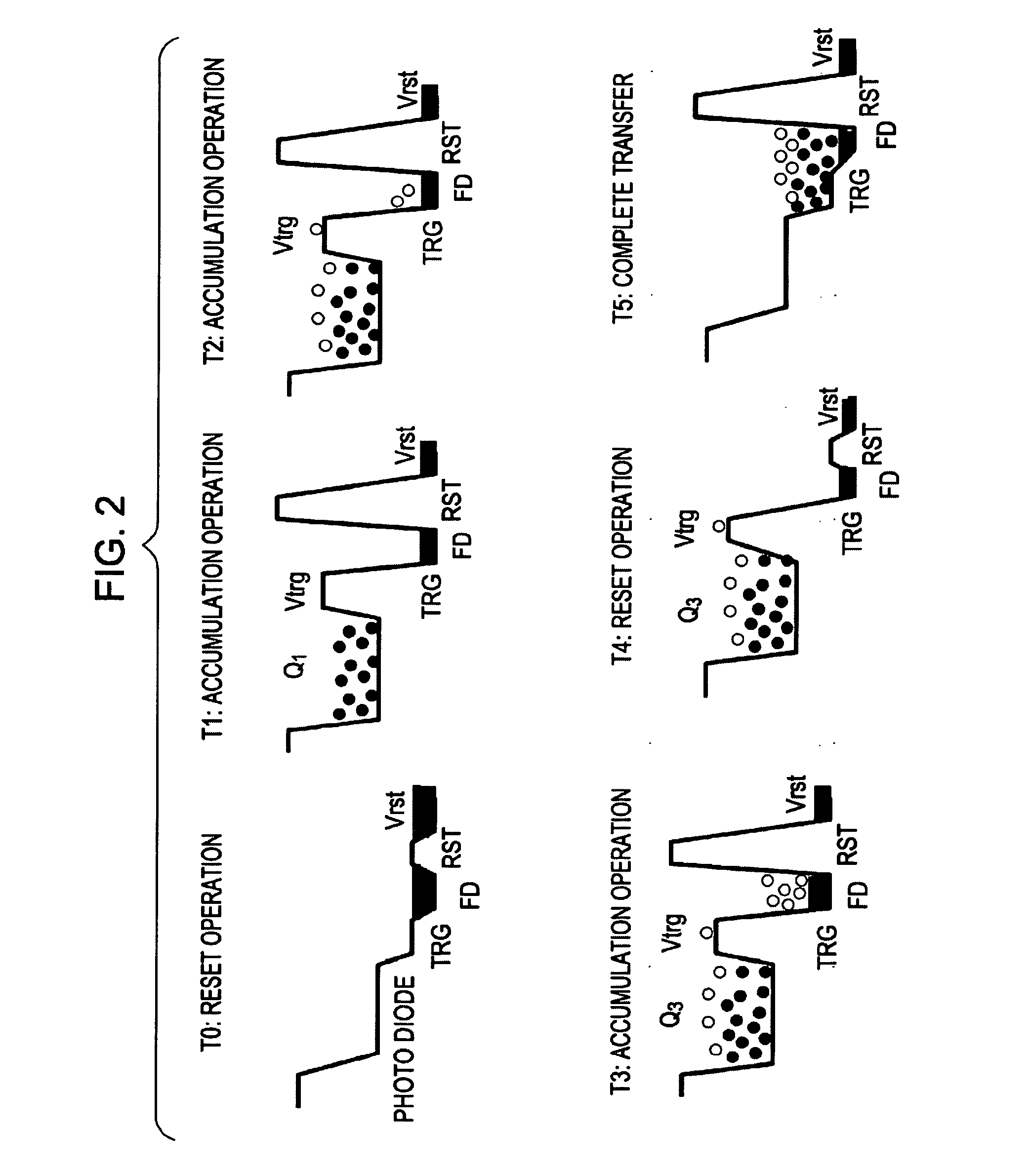
[0067]FIG. 4 is a block diagram showing an example structure of an imaging apparatus as an example of an image processing apparatus according to a first embodiment of the present invention. Light entering through an optical lens 201 is incident on an imaging device 202. The imaging device 202 is composed of, for example, a CMOS image sensor, and photoelectrically converts the incident light into image data. The image data is input to an image processor 203. The imaging device 202 generates two types of images, that is, a long-time exposure image 211 and a short-time exposure image 212, and inputs the two types of image data to the image processor 203. The image processor 203 generates an output image based on the long-time exposure image 211 and short-time exposure image 212. The long-time exposure image 211 and short-time exposure image 212 are different in exposure time.

[0068]First, a process for generating the two types of images, that is, the long-time exposure image 211 and the...

second embodiment

[0148]An imaging apparatus of a second embodiment of the present invention will be described with respect to an example structure in which erroneous detection of a brightness-change pixel is prevented. The second embodiment is different from the first embodiment in the structure of the image analysis unit 302 in the image processor 203. The remaining structure is similar to that of the first embodiment. The overall structure of the imaging apparatus of the second embodiment is similar to that of the first embodiment described with reference to FIG. 4. The image processor 203 according to the second embodiment basically has the structure described with reference FIG. 8, and the pixel value correction unit 303 in the image processor 203 according to the second embodiment also has a structure similar to that described with reference to FIG. 12.

[0149]The second embodiment is different from the first embodiment in the operation of the image analysis unit 302 in the image processor 203. I...

third embodiment

[0172]An image processing apparatus according to a third embodiment of the present invention will be described with respect to an example of modification of the blurred image generation process performed by the intermediate image generator (blurring process) 392 in the pixel value correction unit 303 according to the first embodiment shown in FIG. 12.

[0173]In the first embodiment, as described with reference to FIG. 12, the intermediate image generator (blurring process) 392 in the pixel value correction unit 303 shown in FIG. 12 receives the wide dynamic range image 390 and generates a blurred image using the low pass filter shown in FIG. 11A or 11B by way of example.

[0174]In a case where the subject largely moves, however, the number of taps of the filter increases, and it may be difficult to implement in hardware. In the third embodiment, a blurred image is generated by enlarging and reducing an image. An image is reduced to reduce the amount of information, and the resulting ima...


PUM


Abstract

An image processing apparatus includes the following elements. An image input unit receives a long-time exposure image and a short-time exposure image. An image analysis unit detects a brightness-change pixel in which a brightness change has occurred during a photographic period on the basis of analysis of pixel values in the long-time exposure image and the short-time exposure image. A pixel value correction unit corrects a pixel value of the detected brightness-change pixel. In the pixel value correction unit, a combined image generator selectively combines pixel values in the long-time exposure image and pixel values in the short-time exposure image to generate a combined image; an intermediate image generator generates a blurred image of the combined image; and an output image generator determines a pixel value of the detected brightness-change pixel using a pixel value of a corresponding pixel in each of the combined image and the blurred image.

Description

CROSS REFERENCES TO RELATED APPLICATIONS[0001]The present invention contains subject matter related to Japanese Patent Application JP 2007-059972 filed in the Japanese Patent Office on Mar. 9, 2007, the entire contents of which are incorporated herein by reference.BACKGROUND OF THE INVENTION[0002]1. Field of the Invention[0003]The present invention relates to an image processing apparatus, an imaging apparatus, and an image processing method, and a computer program. Specifically, the present invention relates to an image processing apparatus, an imaging apparatus, an image processing method, and a computer program in which a high-quality output image is generated on the basis of two types of images, that is, a long-time exposure image and a short-time exposure image.[0004]2. Description of the Related Art[0005]Solid-state imaging elements such as a charge-coupled device (CCD) image sensor and a complementary metal oxide semiconductor (CMOS) image sensor used in video cameras, digita...

Claims


Application Information

Patent Timeline
Patent Type & Authority Applications(United States)
IPC IPC(8): G06K9/40G06T5/00H04N5/235H04N5/243
CPCH04N5/2351H04N5/35581H04N5/2355H04N23/71H04N23/741H04N25/589H04N25/50H04N25/53
Inventor KASAI, MASANORIOIKE, YUSUKE
Owner SONY SEMICON SOLUTIONS CORP
Why Eureka
Try Eureka