Ocular lens, ocular lens with additional lens, and optical device

a technology of ocular lens and optical device, which is applied in the field of ocular lens and ocular lens with an additional lens, can solve the problems of curvature aberration and astigmatism, and the difficulty of ensuring a sufficiently long eye relief, so as to increase the overall length, increase the lens diameter, and ensure the effect of eye reli

Active Publication Date: 2013-11-21
NIKON VISION
View PDF1 Cites 5 Cited by
  • Summary
  • Abstract
  • Description
  • Claims
  • Application Information

AI Technical Summary

Benefits of technology

[0025]The above-described arrangement according to the present invention enables providing an ocular lens and an ocular lens with an additional lens well corrected for aberrations through a sufficiently large angle of view and having a sufficient eye relief while ensuring avoidance of increasing the overall length and suppression of an increase in lens diameter, and an optical device including the ocular lens or the ocular lens with an additional lens.

Problems solved by technology

However, it is well known that, in ordinary cases, when the apparent field of view of an ocular lens is increased, it becomes difficult to secure a sufficiently long eye relief, and aberrations of a luminous flux at the periphery of the field of view, particularly field curvature aberration and astigmatism worsen abruptly.

Method used


Image

  • Ocular lens, ocular lens with additional lens, and optical device
  • Ocular lens, ocular lens with additional lens, and optical device
  • Ocular lens, ocular lens with additional lens, and optical device

Examples


examples

[0091]Six examples will be described below with respect to such ocular lenses 3. FIGS. 3, 5, 7, 9, 11, and 13 are diagrams showing the constructions of ocular lenses 3 in the first to sixth examples.

first example

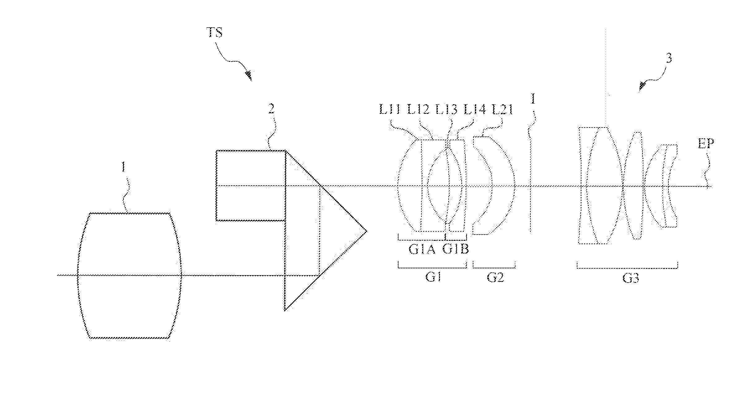
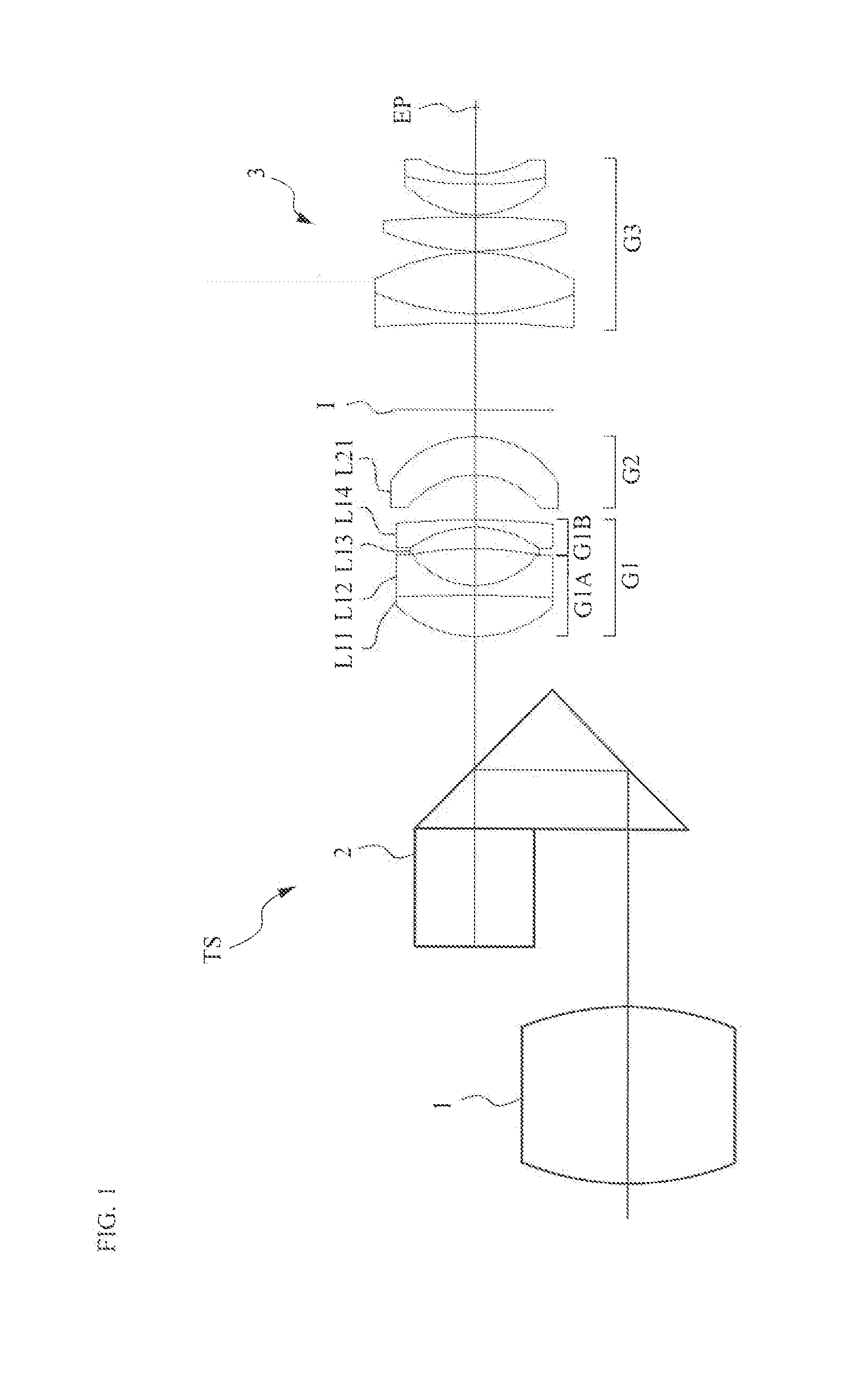
[0092]FIG. 3 shows an ocular lens 3 according to the first example. The ocular lens 3 according to the first example includes, in order from the object side, a first lens group G1 having a negative refractive power, a second lens group G2 having a lens component with a convex surface facing the viewing eye side, and a third lens group G3 having a positive refractive power. An object-side focal plane I of the third lens group G3 is positioned between the second lens group G2 and the third lens group G3. The first lens group G1 includes, in order from the object side, a first lens component G1A in meniscus form having a convex surface facing the object side, and a second lens component G1B.

[0093]The first lens component G1A in the first lens group G1 includes a cemented lens formed of a biconvex lens L11 and a biconcave lens L12 in order from the object side. The second lens component G1B includes a cemented lens formed of a positive meniscus lens L13 and a negative meniscus lens L14 ...

second example

[0098]FIG. 5 shows an ocular lens 3 according to the second example. The ocular lens 3 according to the second example includes, in order from the object side, a first lens group G1 having a negative refractive power, a second lens group G2 having a lens component with a convex surface facing the viewing eye side, and a third lens group G3 having a positive refractive power. An object-side focal plane I of the third lens group G3 is positioned between the second lens group G2 and the third lens group G3. The first lens group G1 includes, in order from the object side, a first lens component G1A in meniscus form having a convex surface facing the object side, and a second lens component G1B.

[0099]The first lens component G1A in the first lens group G1 includes a cemented lens formed of a biconvex lens L11 and a b concave lens L12 in order from the object side. The second lens component G1B includes a cemented lens formed of a planoconvex lens L13 and a biconcave lens L14 in order fro...


PUM


Abstract

The invention provides an ocular lens well corrected for aberrations through a sufficiently large angle of view and having a sufficient eye relief while ensuring avoidance of increasing the overall length and suppression of an increase in lens diameter, and provides an optical device including this ocular lens.An ocular lens 3 includes, in order from an object side, a first lens group G1 including a first lens component G1A in meniscus form having a convex surface facing the object side, a second lens group G2 including a lens component L21 having a convex surface facing a viewing eye side, and a third lens group G3 having a positive refractive power. An object-side focal plane I of the third lens group G3 is positioned between the second lens group G2 and the third lens group G3. When f represents the focal length of the entire system; and f12 represents the combined focal length of the first lens group G1 and the second lens group G2, a condition shown by the following expression:6≦|f12| / f is satisfied.

Description

TECHNICAL FIELD[0001]The present invention relates to an ocular lens, an ocular lens with an additional lens, and an optical device.BACKGROUND ART[0002]For example, in an optical device such as a telescope, a binocular or a microscope, an ocular lens is used to further enlarge and view a real image formed by an objective lens. It is demanded that such an ocular lens have a sufficient eye relief (the on-axis spacing between the outermost lens surface of the ocular lens on the viewing eye side and the eye point (the position of the viewing eye) for comfortable viewing, as well as that the lens be well corrected for aberrations through a large angle of view. However, it is well known that, in ordinary cases, when the apparent field of view of an ocular lens is increased, it becomes difficult to secure a sufficiently long eye relief, and aberrations of a luminous flux at the periphery of the field of view, particularly field curvature aberration and astigmatism worsen abruptly.[0003]For...

Claims


Application Information

Patent Timeline
Patent Type & Authority Applications(United States)
IPC IPC(8): G02B9/12G02B9/34
CPCG02B9/12G02B9/34G02B25/001G02B3/12G02B3/00
Inventor FUKUMOTO, SATOSHI
Owner NIKON VISION
Why Eureka
Try Eureka