Image display device and eyepiece optical system

a display device and optical system technology, applied in optics, magnifying glasses, instruments, etc., can solve the problems of reduced light amount, deterioration of the field-of-view angle characteristics of the image display element, and inability to observe the image with the correct color

Active Publication Date: 2020-06-18
CANON KK
View PDF0 Cites 4 Cited by
  • Summary
  • Abstract
  • Description
  • Claims
  • Application Information

AI Technical Summary

Benefits of technology

[0009]a surface of the first lens on the image display element side has an aspherical shape having a convex shape in a region including an optical axis of

Problems solved by technology

If the emission angle from the image display element increases, field-of-view angle characteristics of the image display element deteriorates and an image with correct color cannot be observed.
Further, an incidence angle of a polarization element such as a polarization plate, a λ/4 plate, and a polarizing beam splitter (PBS) in the eyepiece optic

Method used


Image

  • Image display device and eyepiece optical system
  • Image display device and eyepiece optical system
  • Image display device and eyepiece optical system

Examples


first exemplary embodiment

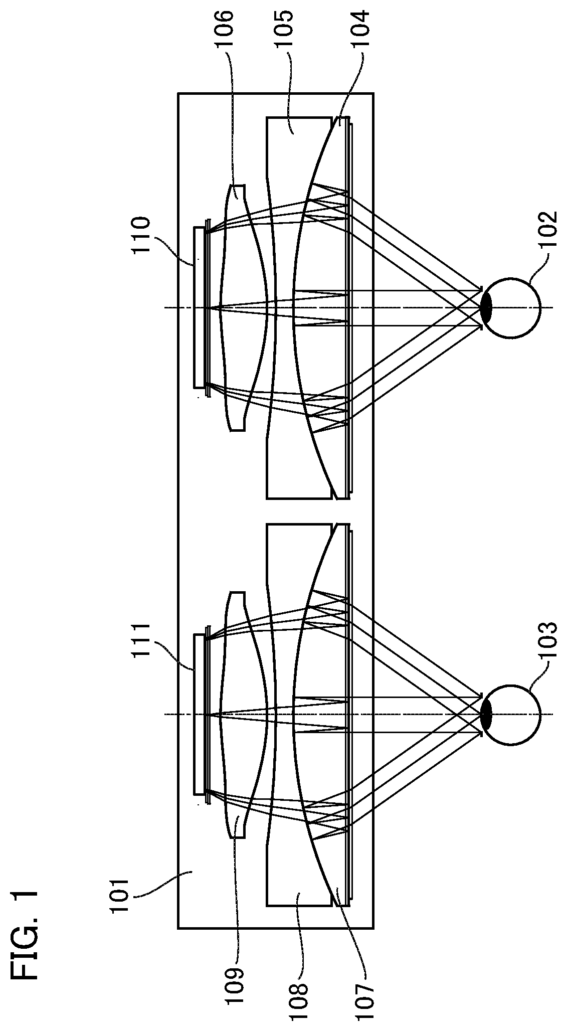
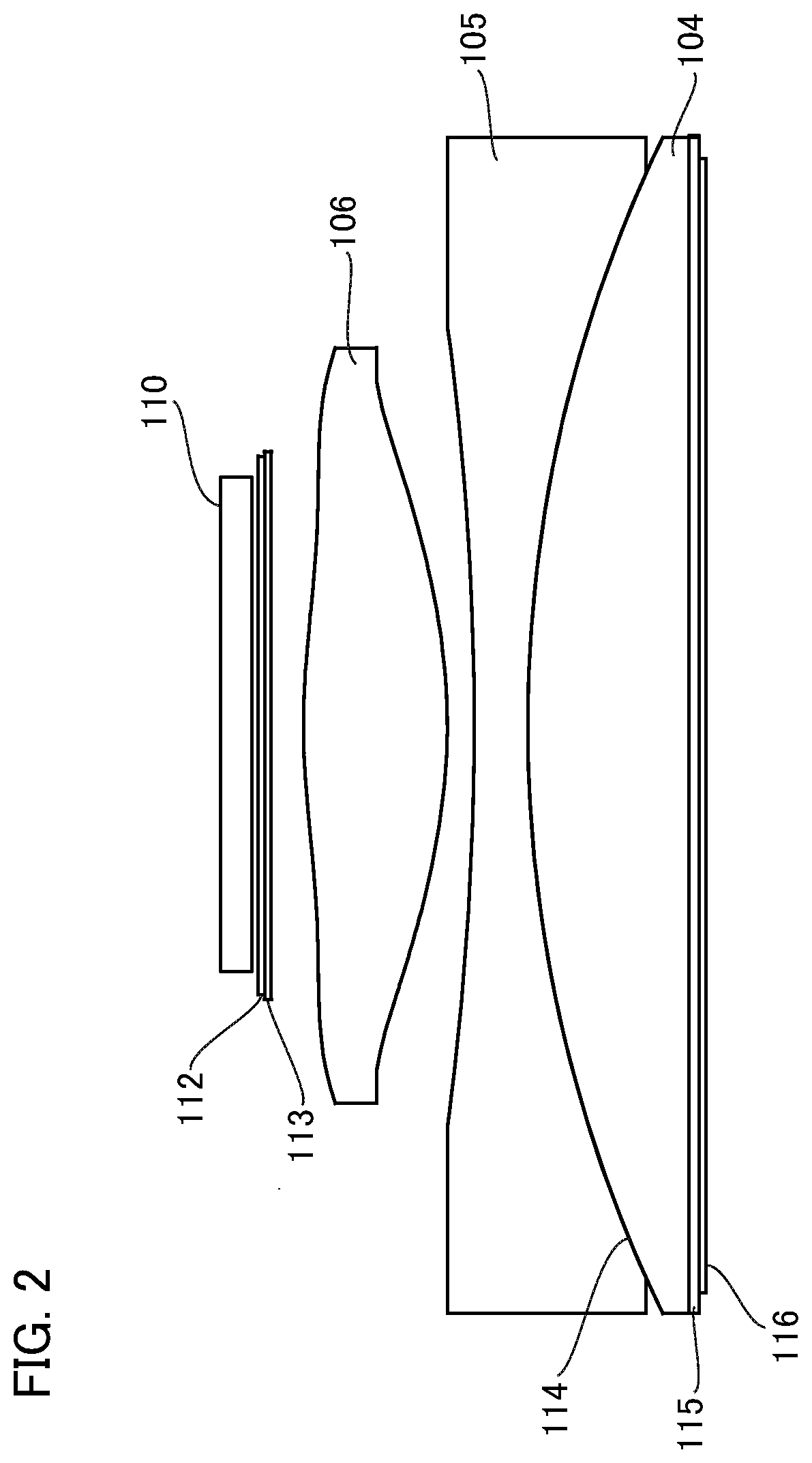
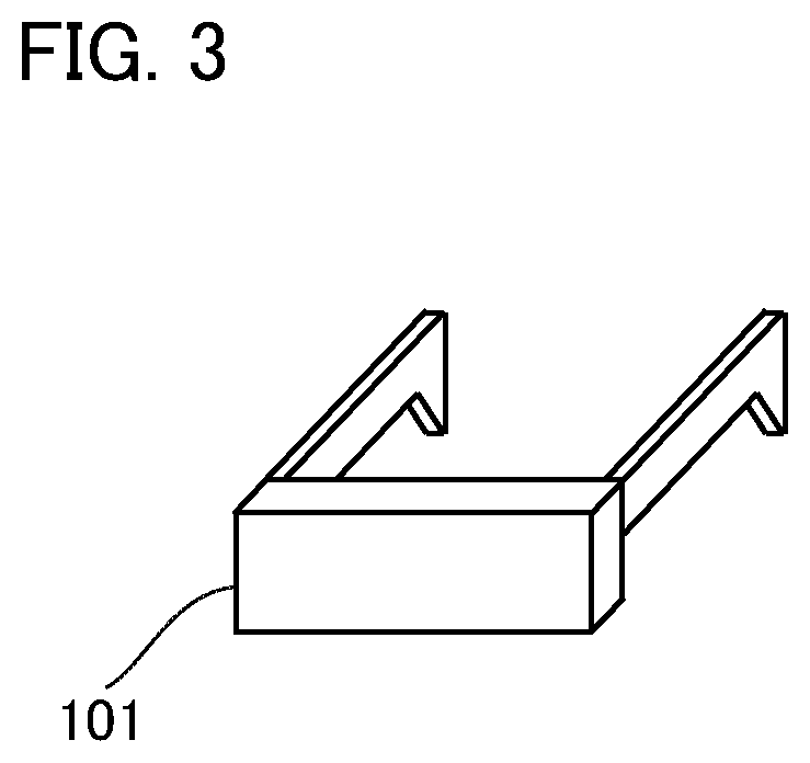
[0026]A configuration of an image display device according to a first exemplary embodiment will be described with reference to an eyepiece optical system of the image display device in FIG. 1. FIG. 1 is a schematic diagram of the image display device according to the first exemplary embodiment. In FIG. 1, 101 denotes an HMD as an image display device, 102 denotes a right eye of an observer, and 103 denotes a left eye of the observer. A lens 104, a lens 105, and a lens 106 constitute a right-eye eyepiece optical system, and a lens 107, a lens 108, and a lens 109 constitute a left-eye eyepiece optical system. 110 denotes a right-eye image display element, 111 denotes a left-eye image display element, and the image display elements are organic EL (Electroluminescence) displays.

[0027]The right-eye eyepiece optical system magnifies and projects an original image displayed on the right-eye image display element 110 as a virtual image and guides the image to the right eye 102 of the observ...

second exemplary embodiment

[0064]A configuration of an image display device according to a second exemplary embodiment will be described with reference to an eyepiece optical system of an image display device in FIG. 8. FIG. 8 is a schematic diagram of the image display device according to the second exemplary embodiment. In FIG. 8, 201 denotes an HMD, 202 denotes a right eye of an observer, and 203 denotes a left eye of the observer. A lens 204 and a lens 205 constitute a right-eye eyepiece optical system, and a lens 206 and a lens 207 constitute a left-eye eyepiece optical system. 208 denotes a right-eye image display element, 209 denotes a left-eye image display element, and these image display elements are organic EL displays.

[0065]The right-eye eyepiece optical system magnifies and projects an original image displayed on the right-eye image display element 208 as a virtual image and guides the image to the right eye 202 of the observer. The left-eye eyepiece optical system magnifies and projects an origi...

third exemplary embodiment

[0095]A configuration of an image display device according to a third exemplary embodiment will be described with reference to an eyepiece optical system of an image display device in FIG. 11. FIG. 11 is a schematic diagram of the image display device according to the third exemplary embodiment. In FIG. 11, 301 denotes an HMD, 302 denotes a right eye of an observer, and 303 denotes a left eye of the observer. A lens 304 and a lens 305 constitute a right-eye eyepiece optical system, and a lens 306 and a lens 307 constitute a left-eye eyepiece optical system. 308 indicates a right-eye image display element, 309 indicates a left-eye image display element, and the image display element are organic EL displays.

[0096]The right-eye eyepiece optical system magnifies and projects an original image displayed on the right-eye image display element 308 as a virtual image and guides the image to the right eye 302 of the observer. The left-eye eyepiece optical system magnifies and projects an ori...


PUM


Abstract

provided is an image display device that can reduce deterioration in image quality in a peripheral portion of an eyepiece optical system, includes an eyepiece optical system having a polarization element and guiding light from an image display element toward eyeballs of an observer, in which the eyepiece optical system includes a first lens for determining an emission angle from the image display element, and a surface of the first lens on the image display element side has an aspherical shape having a convex shape in a region including an optical axis of the first lens, wherein the aspherical shape has an inflection point within an optically effective region in a cross section including the optical axis, and wherein an eye relief E of the eyepiece optical system satisfies 15 mm≤E≤25 mm.

Description

BACKGROUND OF THE INVENTIONField of the Invention[0001]The present invention relates to an image display device and an eyepiece optical system.Description of the Related Art[0002]Development of head-mounted displays is underway, for example, for the purpose of virtual reality (VR) or enabling an observer to immerse oneself into an observed image on a large screen alone. For an image display device that is used for a head-mounted display (HMD) or the like, presentation of an image with a wide angle of view is desired in order to allow natural observation and increase a sense of presence. Further, it is preferable for a head-mounted image display device to have a small thickness and weight.[0003]An eyepiece optical system that folds an optical path using polarization has been proposed as a technology for achieving presentation of an image with a wide angle of view. If an eyepiece optical system having a wide angle of view is realized using this polarization, a focal length of the eyep...

Claims


Application Information

Patent Timeline
IPC IPC(8): G02B25/00G02B27/01
CPCG02B25/001G02B2027/0127G02B27/0172
Inventor TOHARA, MASAKAZUKONDO, RYOJI
Owner CANON KK
Why Eureka
Try Eureka