Multicast system for forwarding desired multicast packets in a computer network

a multicast system and computer network technology, applied in data switching networks, special service provisioning for substations, digital transmission, etc., can solve problems such as unwanted redundancy of traffi

Inactive Publication Date: 2005-01-25
CISCO TECH INC
View PDF10 Cites 98 Cited by
  • Summary
  • Abstract
  • Description
  • Claims
  • Application Information

AI Technical Summary

Benefits of technology

The invention gets rid of the unnecessary multicast group traffic forwarded to multicast routers by a layer 2 switch, by configuring the Layer 2 switch forwarding table to list only the routers which need packets of a particular group.

Problems solved by technology

This redundant traffic is unwanted.

Method used


Image

  • Multicast system for forwarding desired multicast packets in a computer network
  • Multicast system for forwarding desired multicast packets in a computer network
  • Multicast system for forwarding desired multicast packets in a computer network

Examples


Embodiment Construction

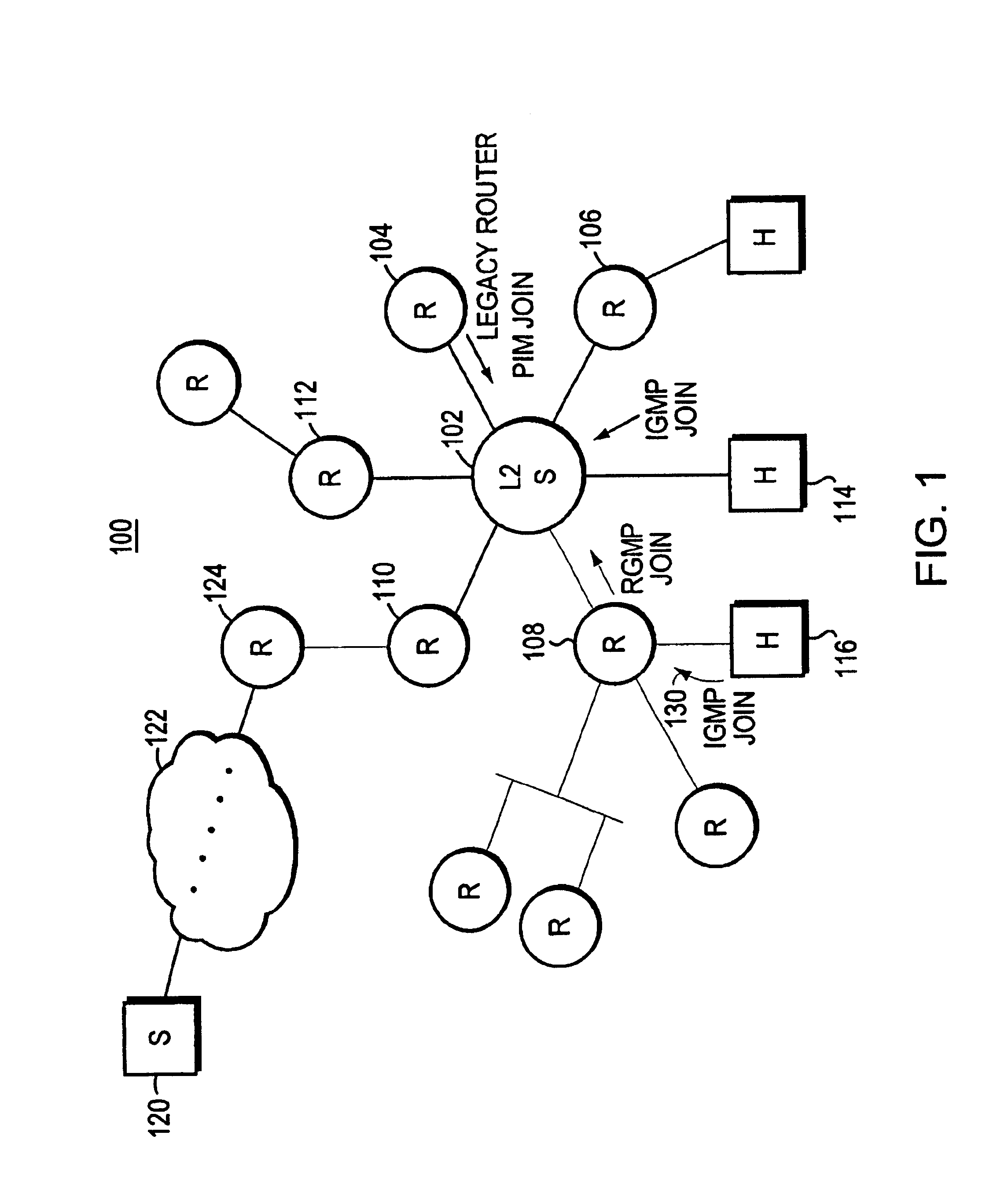
Computer network 100 is shown in FIG. 1. Computer network 100 has a Layer 2 switch 102 which switches packets using Layer 2 protocol.

Various ports of switch 102 are connected to routers. For example, Layer 2 switch 102 connects to legacy router 104. Legacy router 104 does not implement the invention, as will be explained in greater detail herein below.

Also connected to Layer 2 switch 102 are routers which implement the invention, including router 106, router 108, router 110, and router 112. Also, a host computer 114 is shown connected to a port of Layer 2 switch 102.

Source computer end station 120 transmits packets belonging to a multicast group. The multicast group packets are transported, for example, through network cloud 122, to router 124. Router 124 in turn connects to router 110, and router 110, connects to a port of Layer 2, switch 102. The multicast packets transmitted by source end station 120 contain a multicast destination address in their Layer 2 address, that is the MA...


PUM


Abstract

A method and apparatus for a router to inform a Layer 2 switch by use of packets of a new router group port management protocol (RGMP) that the layer 2 switch is to forward multicast packets of a specified group to the router. First the router transmits a RGMP HELLO packet to the layer 2 switch to inform the switch that the router is a multicast router implementing the invention. Then, in the event that the router receives an IGMP packet from an end station requesting multicast packets of a particular group, in response the router sends an RGMP JOIN packet to the layer 2 switch. The RGMP JOIN packet requests that the layer 2 switch forward only multicast group packets, of the group whose group number is written into a field of the RGMP JOIN packet, to the router. Also, the router sends a prior art PIM JOIN packet to other multicast routers in order to be placed on the multicast distribution tree for that group. The layer 2 switch builds a forwarding table for multicast groups listing ports connected to routers having sent a RGMP JOIN for that group. When a multicast group packet arrives at the layer 2 switch, the switch uses the forwarding table to forward the packet only to those routers requesting that group.

Description

BACKGROUND OF THE INVENTION1. Field of the InventionThis invention relates to multicast groups in a computer network, and more particularly to transmission of multicast groups from a router through a layer 2 switch to another router, which then distributes the packets to further downstream routers or to end stations.2. Background InformationA network exchange point is often designed with a Layer 2 switch interconnecting a plurality of fast routers. The Layer 2 switch has a plurality of ports, and usually one router is connected to one port of the Layer 2 switch. Also, an end station may be directly connected to the Layer 2 switch.An end node is spoken of as “desiring” to receive multicast packets of a particular multicast group, for example, in response to a user (person) executing a command to begin receiving the multicast group packets. An end node desiring to receive multicast group packets sends a relatively simple packet, referred to as an Internet Group Management Packet (IGMP...

Claims


Application Information

Patent Timeline
Patent Type & Authority Patents(United States)
IPC IPC(8): H04L12/18
CPCH04L12/185
Inventor WU, ISHANCHANDIKA, NAGARANIMELLACHERUVA, RAMANACAI, YIQUN
Owner CISCO TECH INC
Why Eureka
Try Eureka