Methods and systems for machine monitoring system calibration

a technology of machine monitoring and system calibration, applied in the field of machine monitoring systems, can solve problems such as inaccuracy of measurement methods

Inactive Publication Date: 2005-02-01
GENERAL ELECTRIC CO
View PDF14 Cites 32 Cited by
  • Summary
  • Abstract
  • Description
  • Claims
  • Application Information

AI Technical Summary

Problems solved by technology

However, known calibration methods may introduce measurement inaccuracies related to characteristics inherent to a selected calibration probe measurement technology, to calibration probe placement in a different location than the monitoring system probe and / or to temperature expansion and rotational dynamics effects differences between the operating condition and the shutdown condition.

Method used


Image

  • Methods and systems for machine monitoring system calibration
  • Methods and systems for machine monitoring system calibration
  • Methods and systems for machine monitoring system calibration

Examples


Embodiment Construction

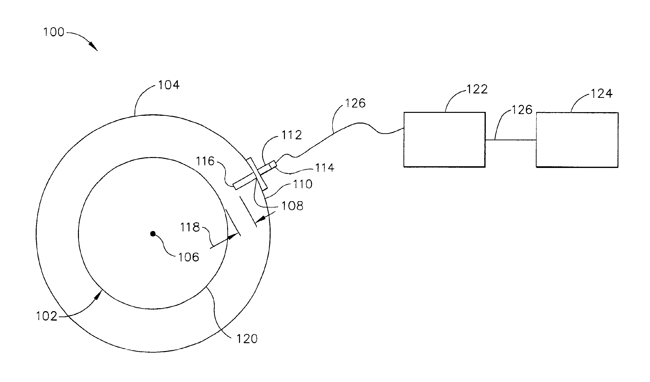
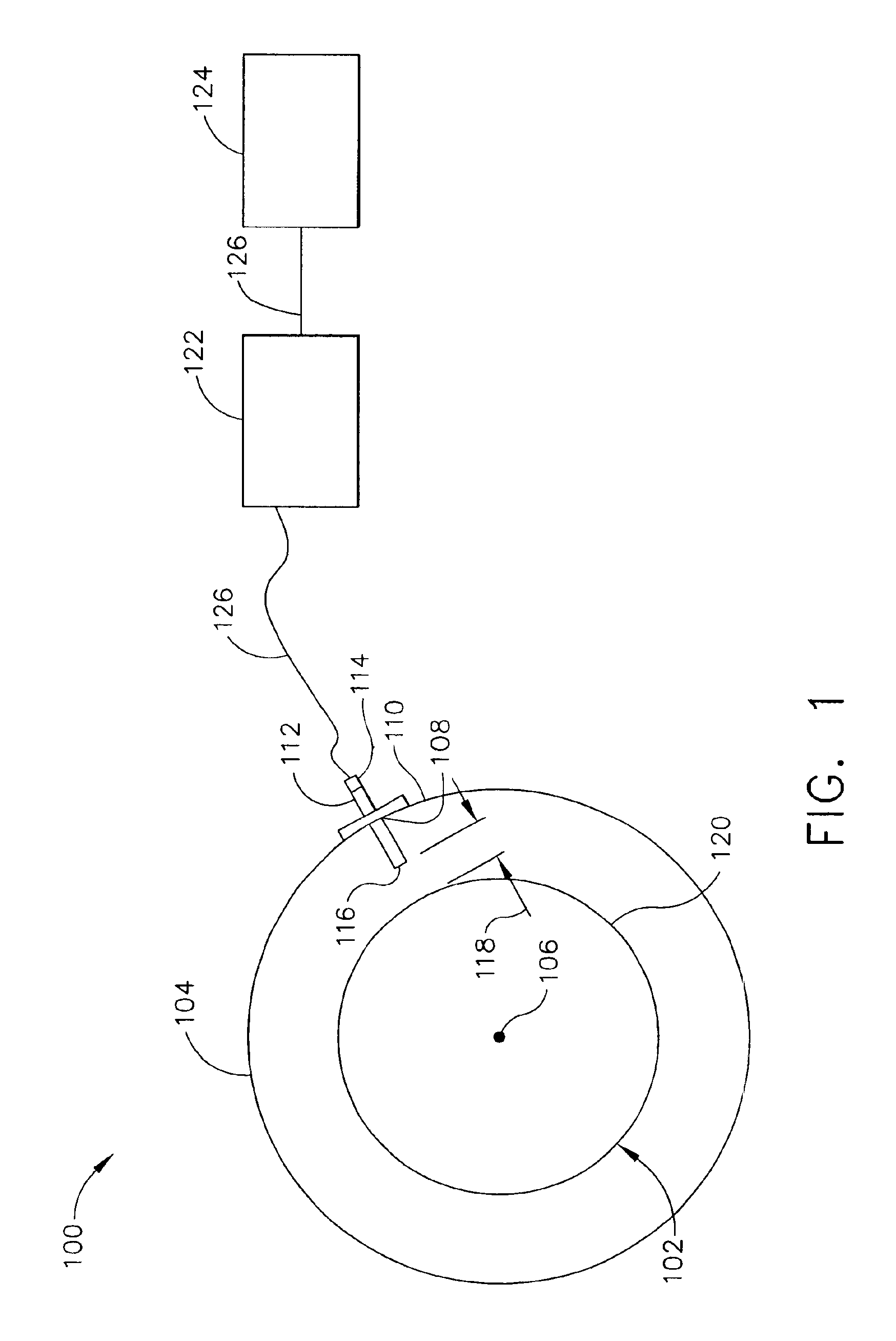
FIG. 1 is a perspective end view of an exemplary rotary machine 100. In the exemplary embodiment, machine 100 is a gas turbine such as a Model 9H, or 9FA, commercially available from General Electric, Greenville, S.C. Machine 100 includes a rotatable member 102 and a stationary member 104. Rotatable member 102 may include radially extending members (not shown), such as, but not limited to turbine blades, and is configured to rotate about a longitudinal axis 106. Stationary member 104 includes at least one aperture 108 through a casing 110. In the exemplary embodiment, aperture 108 includes a mounting adapter 112. In an alternative embodiment, aperture 108 is threaded to receive a capacitance proximity probe 114 directly. Probe 114 extends radially inwardly through aperture 108 toward rotatable member 102. A sensing end 116 of probe 114 is positioned a predetermined distance 118 from an outer periphery 120 of rotatable member 102. Probe 114 is electrically coupled to an electronic co...


PUM


Abstract

A method of measuring a clearance distance between a first member and a stationary member is provided. The method includes measuring the clearance distance using a first probe that is removably coupled at least partially within a mounting adapter, determining a first probe calibration based on the measured clearance distance, measuring a gauge clearance distance using a second probe, and modifying the first probe calibration based on the gauge clearance distance.

Description

BACKGROUND OF THE INVENTIONThis invention relates generally to machine monitoring systems, and more particularly to a monitoring system calibration.At least some known machines use capacitance probe-based clearance monitoring systems to measure member clearances. Specifically, one such monitoring system used in determining turbine blade tip clearance measurement uses a capacitance probe. To ensure the monitoring system is outputting correct clearance distance values, the monitoring system output may be periodically checked against a standard, such as, a calibration system of traceable accuracy characteristics. At least some known machines include rotating members that make access to portions of the monitoring system during machine operational conditions impracticable. Hence, the machine monitoring system may be calibrated during machine shutdown conditions. However, known calibration methods may introduce measurement inaccuracies related to characteristics inherent to a selected cal...

Claims


Application Information

Patent Timeline
Patent Type & Authority Patents(United States)
IPC IPC(8): G01B5/14G01B7/14
CPCG01B7/14G01B5/14
Inventor KIRZHNER, JOSEPH DMITRY
Owner GENERAL ELECTRIC CO
Why Eureka
Try Eureka