Integrated actuator assembly for pivot style multi-roll leveler

a technology of actuator assembly and pivot style, applied in the field of levelers, can solve the problems of difficult to exert uniform force across the width of the strip, undesirable shape defects in the finished strip, so as to reduce the amount of head scrap, the material yield required to produce a flat strip is minimized, and the variance of coil to coil is improved

Inactive Publication Date: 2005-02-01
MACHINE CONCEPTS
View PDF18 Cites 9 Cited by
  • Summary
  • Abstract
  • Description
  • Claims
  • Application Information

AI Technical Summary

Benefits of technology

The present invention provides this ability. The present invention consists of a multi-roll leveler having a closed-loop control system. The leveler of the present invention utilizes a shape sensor located at the exit thereof. The shape sensor measures the stresses present in and, thus, the flatness across the width of the strip. Shape sensor readings are fed back to a microprocessor-based controller that uses the readings to ascertain and initiate necessary changes to one or more of various leveler settings. The shape sensor is preferably disposed substantially across the width of the leveler, and may be divided along its length into a number of individual measurement segments. In one particular embodiment of the precision leveler of the present invention, there are also preferably a number of work roll adjusting means disposed along the width of the leveler, such as, for example, the motor-driven jack assemblies and adjusting wedge pairs discussed above. One or more of the shape sensor measurement segments forms a measurement zone along a portion of the width of the metal strip. At least one measurement zone is preferably associated with each of the plurality of work roll adjusting means. A stress (flatness) measurement is taken by each segment of the measurement zone. The individual measurements may be averaged together or otherwise analyzed to dete...

Problems solved by technology

However, the hot rolling process may also impart undesirable shape defects to the resulting metal strip.
However, it is difficult to exert a uniform force across the width of the strip during the hot rolling process.
Consequently, the finished strip may possess undesirable shape defects.
These shape defects are commonly the result of stresses developed within the strip as it passes through a rolling mill and is subjected to the non-uniform application of force across its width, thereby leading to a non-uniform stretching of the length of the strip.
Because the adjusting me...

Method used


Image

  • Integrated actuator assembly for pivot style multi-roll leveler
  • Integrated actuator assembly for pivot style multi-roll leveler
  • Integrated actuator assembly for pivot style multi-roll leveler

Examples


Embodiment Construction

)

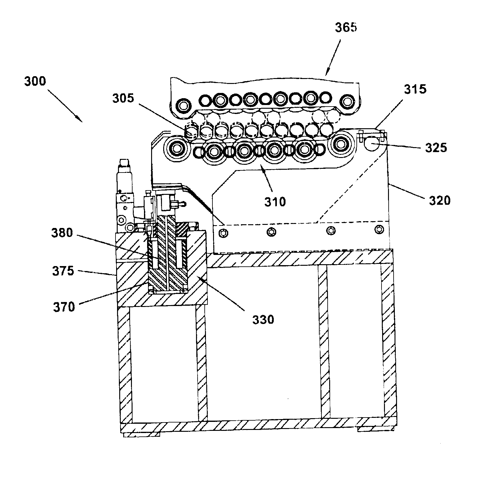
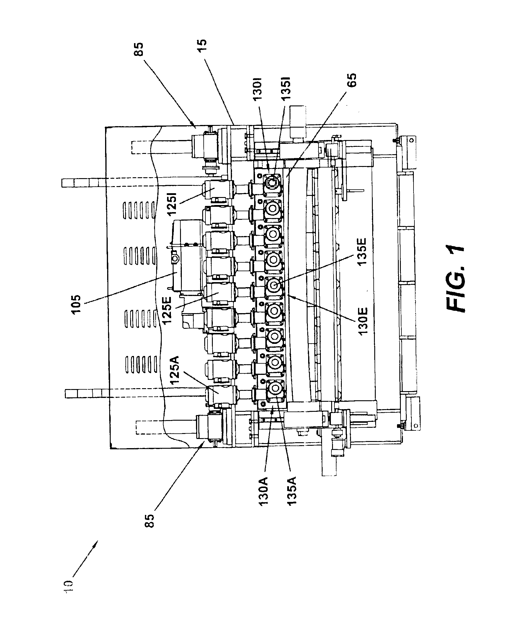
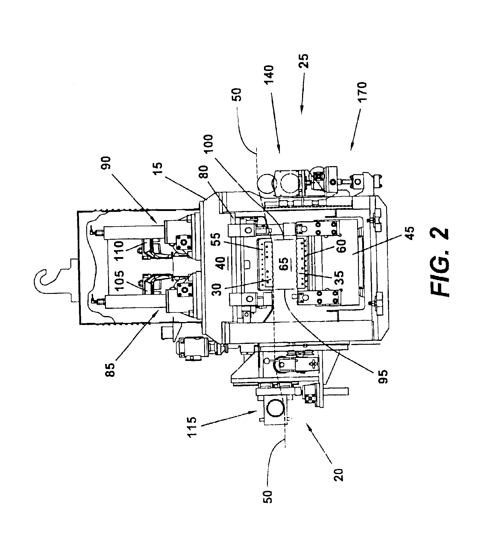
An exemplary embodiment of a leveler with automatic shape control 10 can be seen in FIGS. 1-7. The leveler 10 is shown to include a frame 15. The leveler 10 has an entry 20 and an exit 25 side. A top and bottom set of work rolls 30, 35 are disposed between a set of platens 40, 45 within the frame 15 of the leveler 10, such that they reside between the entry 20 and exit 25 thereof. The sets of work rolls 30, 35 are provided to flatten the metal strip material 50 that will be passed through the leveler 10.

In this embodiment of the present invention, each set of work rolls 30, 35 is supported by a set of backup rollers 55, 60—although it may also be possible to eliminate the backup rollers in other embodiments. In this particular embodiment of the leveler 10, the backup rollers 55, 60 are segmented, so that each work roll is actually supported by a plurality of individual backup rollers. A working envelope 65 is formed within the leveler 10 between the entry 20 and exit 25 side thereo...


PUM

PropertyMeasurementUnit
Forceaaaaaaaaaa

Abstract

A cassette assembly for a multi-roll leveler and a method for producing necessary work roll bending in such a cassette assembly. An upper and lower cassette module are provided for placement into a precision leveler. The lower cassette module is provided with roller support arms that lie below and transverse the work rolls of the module. The roller support-arms are pivotally connected to the lower cassette module near one side thereof. An actuator, or actuators, are integrally located in the lower cassette module to provide an upward force near the ends of the roller support arms opposite that of the pivotal connection. The upward force of the actuator(s) causes a resultant upward displacement of the roller support arms, and a corresponding bending of the work rolls of the lower cassette. The movement of the actuator(s) may be controlled and/or monitored by an automatic shape control system portion of the leveler to which the cassette assembly is installed.

Description

BACKGROUND AND SUMMARY OF THE INVENTIONThe present invention relates to a leveler for the flattening and stress reduction of a metal strip. More specifically, the present invention is a multi-roll leveler with built-in shape control. The leveler is particularly useful, for example, in conjunction with the rolling process often utilized in the manufacturing of metal strip products.During the manufacturing of metal sheet or strip products, various materials are combined, heated, and transformed into a molten metal compound. The molten metal is then generally molded into specific shapes, such as slabs or billets. The molded shapes may then be transported to a hot rolling mill where they can be rolled into thinner products. The molded shape may be reheated in a furnace prior to the rolling process. A molded shapes may be passed through the rolling mill multiple times. The rolling mill may convert the molded shape, typically a slab, into a thin sheet, which may then be rolled into a coil...

Claims


Application Information

Patent Timeline
IPC IPC(8): B21D1/06B21D1/02B21D1/00
CPCB21D1/06B21D1/02
Inventor BERGMAN, GUIL C.ENNEKING, ANTHONY D.
Owner MACHINE CONCEPTS
Why Eureka
Try Eureka