Processes of determining torque output and controlling power impact tools using a torque transducer

a technology of torque transducer and torque output, which is applied in the direction of force/torque/work measurement apparatus, manufacturing tools, instruments, etc., can solve the problems of lack of electronic control of mechanical impact wrenches, inability to accurately determine peak torque, and inability to accurately measure torqu

Inactive Publication Date: 2005-02-01
CHICAGO PNEUMATIC TOOL
View PDF9 Cites 76 Cited by
  • Summary
  • Abstract
  • Description
  • Claims
  • Application Information

AI Technical Summary

Benefits of technology

The foregoing and other features and advantages of the invention will be apparent from the following more particular description of preferred embodiments of the invention.

Problems solved by technology

This phenomena is caused by the inconsistent nature of the force component of the impact.
In either case outlined above, the force may not be the peak force and, hence, the peak torque derived may not be accurate.
Unfortunately, torque measurement accuracy remains diminished.
Another shortcoming of the related art is the lack of an electronic control in a mechanical impact wrench.

Method used


Image

  • Processes of determining torque output and controlling power impact tools using a torque transducer
  • Processes of determining torque output and controlling power impact tools using a torque transducer
  • Processes of determining torque output and controlling power impact tools using a torque transducer

Examples


Embodiment Construction

Although certain preferred embodiments of the present invention will be shown and described in detail, it should be understood that various changes and modifications may be made without departing from the scope of the appended claims. The scope of the present invention will in no way be limited to the number of constituting components, the materials thereof, the shapes thereof, the relative arrangement thereof, etc., which are disclosed simply as an example of the preferred embodiment.

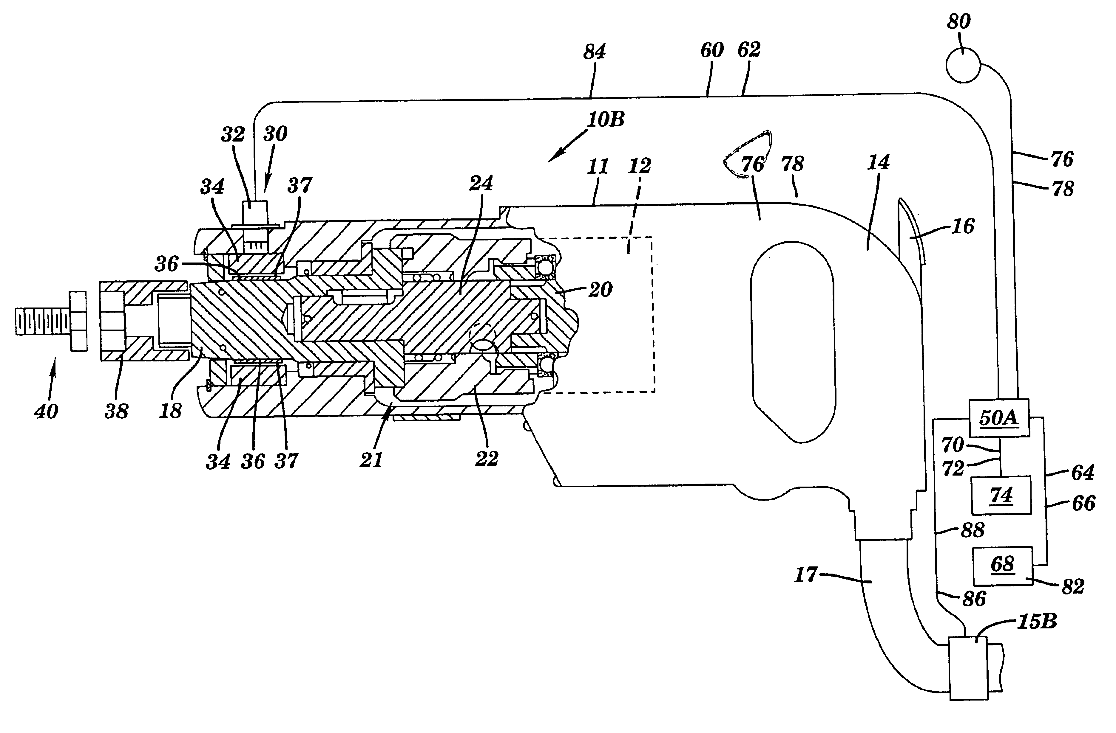
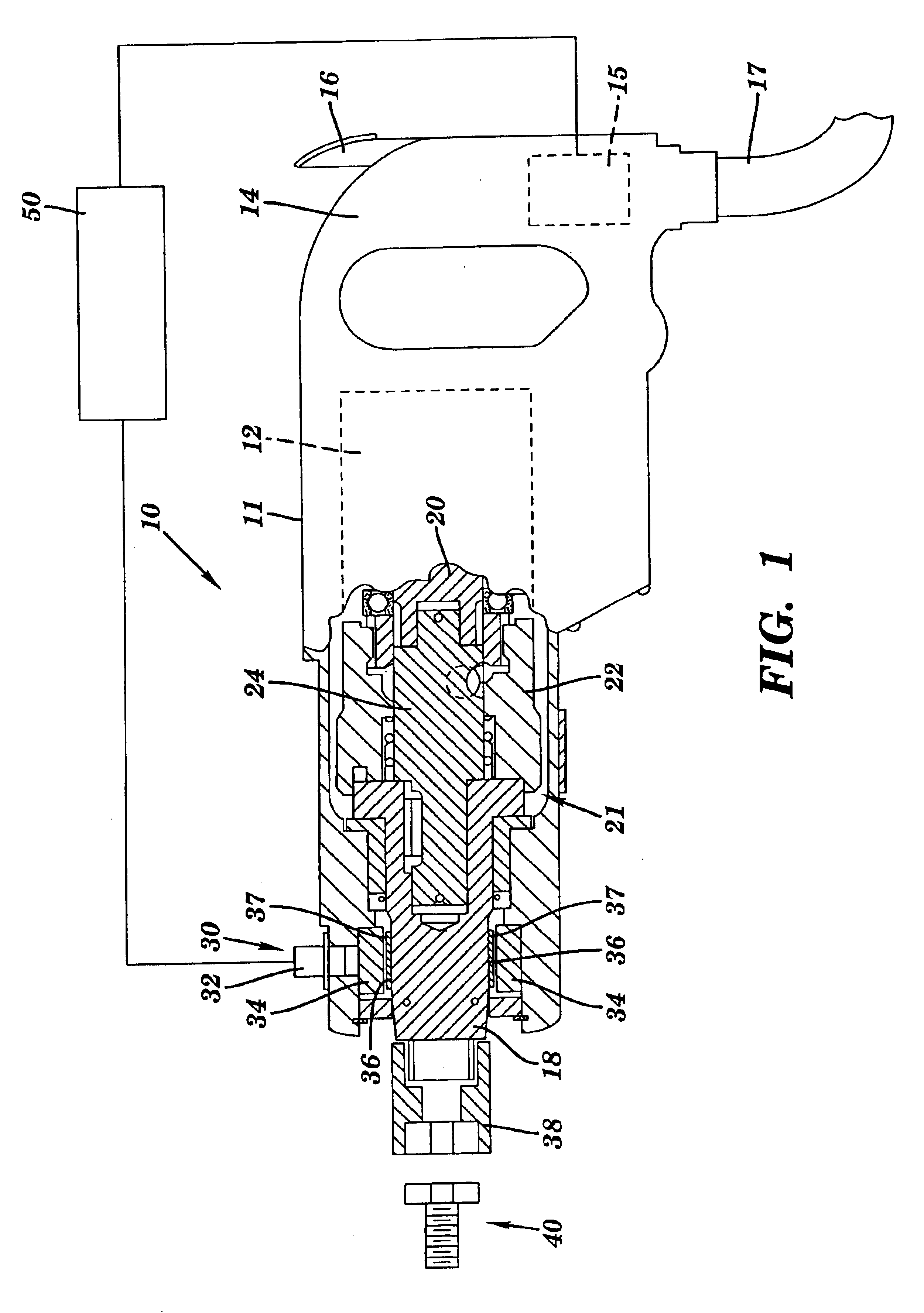
Referring to FIG. 1, a power impact tool 10 in accordance with the present invention is shown. It should be recognized that while power impact tool 10 is exemplified in the form of a mechanical impact wrench, the teachings of the present invention have applicability to a diverse range of power impact tools. Hence, although the teachings of the present invention provide particular advantages to a mechanical impact wrench, the scope of the invention should not be limited to such devices.

The power tool 10...


PUM


Abstract

An impact tool having a control system for turning off a motor at a preselected torque level.

Description

BACKGROUND OF THE INVENTION1. Technical FieldThe present invention relates to processes for determining torque output and controlling power impact tools. The invention also relates to a mechanical impact wrench having electronic control.2. Related ArtIn the related art, control of power impact tools has been accomplished by directly monitoring the torque of impacts of the tool. For instance, in U.S. Pat. Nos. 5,366,026 and 5,715,894 to Maruyama et al., incorporated herein by reference, controlled impact tightening apparatuses are disclosed in which complex processes involving direct torque measurement are used. Direct torque measurement involves the measurement of the force component of torsional stress, as exhibited by a magnetic field about a tool output shaft, at the point in time of impact. From this force component, related art devices directly determine the torque applied during the impact, i.e., torque T=force F times length of torque arm r. As exemplified by FIG. 10 of U.S. ...

Claims


Application Information

Patent Timeline
Patent Type & Authority Patents(United States)
IPC IPC(8): B25B23/14B25D17/10
CPCB25B23/1405
Inventor GIARDINO, DAVID A.
Owner CHICAGO PNEUMATIC TOOL
Why Eureka
Try Eureka