Fuel injector nozzle assembly with induced turbulence

a fuel injector and turbulence technology, applied in the direction of fuel injection apparatus, spraying apparatus, feeding system, etc., can solve the problems of wall wetting and piston wetting, cost and packaging concerns, and current low pressure system does not provide optimal fuel atomization

Inactive Publication Date: 2005-02-01
VISTEON GLOBAL TECH INC
View PDF20 Cites 45 Cited by
  • Summary
  • Abstract
  • Description
  • Claims
  • Application Information

AI Technical Summary

Problems solved by technology

However, this requires the use of a secondary high pressure fuel pump, which causes cost and packaging concerns.
Additionally, injecting the fuel at high pressure causes the fuel to propagate into the piston cylinder causing wall wetting and piston wetting concerns.
Traditional low pressure direct injection systems do not present the wall wetting and piston wetting problems associated with high pressure systems, however, current low pressure systems do not provide optimum fuel atomization.

Method used


Image

  • Fuel injector nozzle assembly with induced turbulence
  • Fuel injector nozzle assembly with induced turbulence
  • Fuel injector nozzle assembly with induced turbulence

Examples


Embodiment Construction

The following description of the preferred embodiments of the invention is not intended to limit the scope of the invention to these preferred embodiments, but rather to enable any person skilled in the art to make and use the invention. The present invention is related to United States Patent application Ser. No. 10 / 043,367 entitled “Fuel Injector Nozzle Assembly”, filed Jan. 9, 2002, which is assigned to the assignee of the present application and is hereby incorporated by reference into this application.

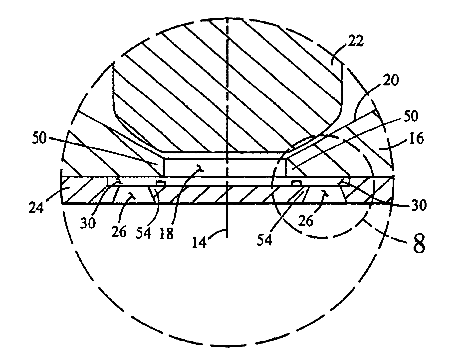
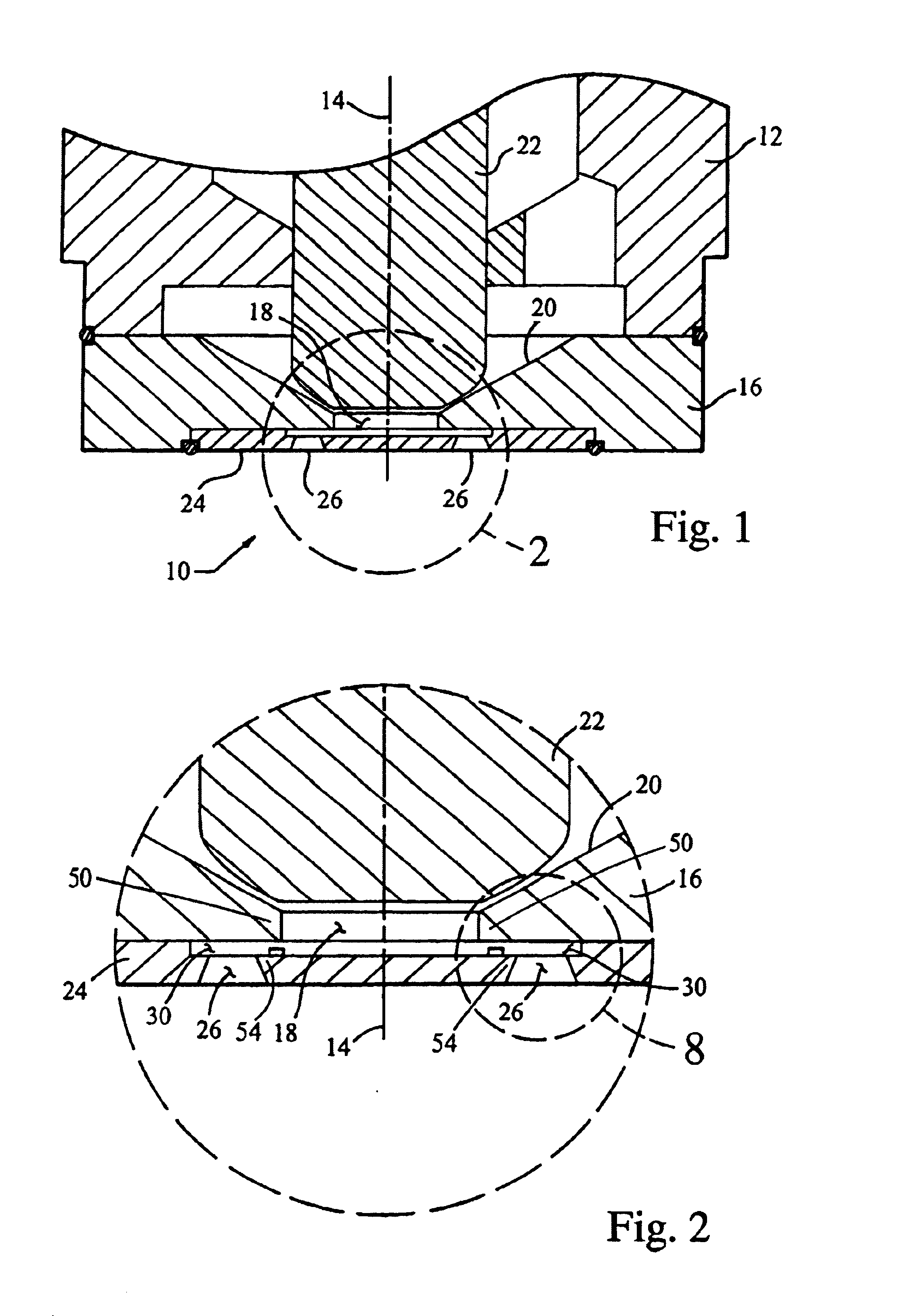
Referring to FIGS. 1-3, a fuel injector nozzle assembly of the preferred embodiment of the present invention is shown generally at 10. The fuel injector nozzle assembly 10 includes an injector body 12 which defines a supply axis 14 through which fuel flows. A distal end of the injector body 12 defines a valve seat 16. The valve seat 16 has a supply passage 18 through which fuel flows outward from the injector body 12. An upper surface 20 of the valve seat 16 is adapted to engage a...


PUM


Abstract

A fuel injector nozzle assembly includes an injector body including a valve seat with a supply passage through which fuel flows generally along a supply axis. A nozzle plate is mounted onto the valve seat and includes a plurality of orifice holes therein through which fuel flows. A turbulence cavity is defined by the nozzle plate and the valve seat wherein fuel flows into the turbulence cavity through the supply passage and out from the turbulence cavity through the plurality of orifice holes. A plurality of obstructions are located within the turbulence cavity directly in front of the orifice holes and are adapted to create turbulence eddies within the flow entering the orifice holes.

Description

TECHNICAL FIELDThe present invention generally relates to a fuel injector nozzle for providing fine atomization of fuel expelled into an internal combustion engine.BACKGROUNDStringent emission standards for internal combustion engines suggest the use of advanced fuel metering techniques that provide extremely small fuel droplets. The fine atomization of the fuel not only improves emission quality of the exhaust, but also improves the cold start capabilities, fuel consumption, and performance. Traditionally, fine atomization of the fuel is achieved by injecting the fuel at high pressures. However, this requires the use of a secondary high pressure fuel pump, which causes cost and packaging concerns. Additionally, injecting the fuel at high pressure causes the fuel to propagate into the piston cylinder causing wall wetting and piston wetting concerns. Traditional low pressure direct injection systems do not present the wall wetting and piston wetting problems associated with high pres...

Claims


Application Information

Patent Timeline
Patent Type & Authority Patents(United States)
IPC IPC(8): F02M61/18F02M61/00F02M61/16
CPCF02M61/162F02M61/1833F02M61/1853F02M61/1806F02M61/166F02M61/168F02M2200/9053
Inventor XU, MIN
Owner VISTEON GLOBAL TECH INC
Why Eureka
Try Eureka