Fuel injector nozzle for reduced coking

a fuel injector and coking technology, applied in the field of internal combustion engines, can solve the problems of obstructing the opening, reducing engine performance, and insufficient injection of fuel, and achieve the effects of increasing the diameter, reducing the cost of fuel injection, and large surface area

Inactive Publication Date: 2011-02-10
INT ENGINE INTPROP CO LLC
View PDF28 Cites 22 Cited by
  • Summary
  • Abstract
  • Description
  • Claims
  • Application Information

AI Technical Summary

Benefits of technology

[0018]The shape of the nozzle holes creates an outside opening that is recessed from the outside surface of the needle housing, which increases the outside opening diameter. The recessed outside opening shields the intermediate opening from exposure to coking in the engine cylinder, and the increased diameter creates a large surface area surrounding the intermediate opening. The overall effect of the exemplary embodiment should result in reduction and prevention of coke accumulation at the intermediate opening and thereby keep the fuel injector functioning effectively for a longer period of time.

Problems solved by technology

The deposit of coke around the nozzle openings can obstruct the opening.
As a result, fuel cannot be adequately injected into the engine cylinder causing lower engine performance in the form of poor acceleration, rough idling, hesitating, stalling and power loss.
The present inventors have recognized one problem encountered by some fuel injectors is coking around the nozzle outlet openings that reduces flow through the holes 132 over time and thereby reduces engine performance.

Method used


Image

  • Fuel injector nozzle for reduced coking
  • Fuel injector nozzle for reduced coking
  • Fuel injector nozzle for reduced coking

Examples


Embodiment Construction

[0027]While this invention is susceptible of embodiment in many different forms, there are shown in the drawings, and will be described herein in detail, specific embodiments thereof with the understanding that the present disclosure is to be considered as an exemplification of the principles of the invention and is not intended to limit the invention to the specific embodiments illustrated.

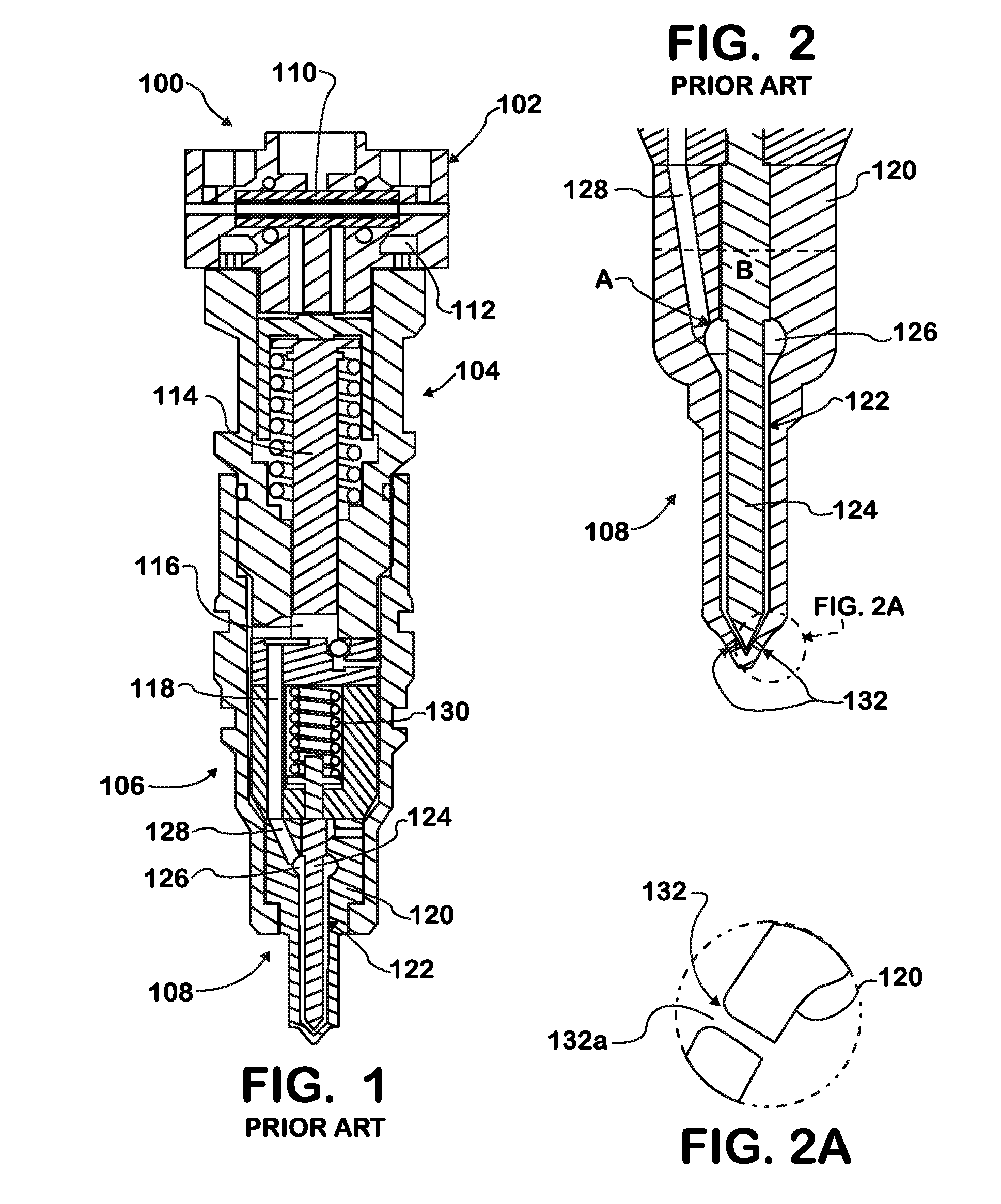
[0028]FIGS. 1 and 2 illustrate the prior art fuel injection needle. In the prior art design, coking around the nozzle holes 132 can reduce flow through the nozzle holes 132 over time and thereby reduces engine performance. The present invention should help alleviate this problem by modifying the nozzle holes 132.

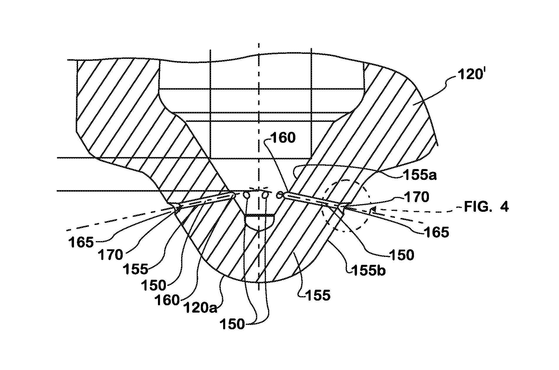
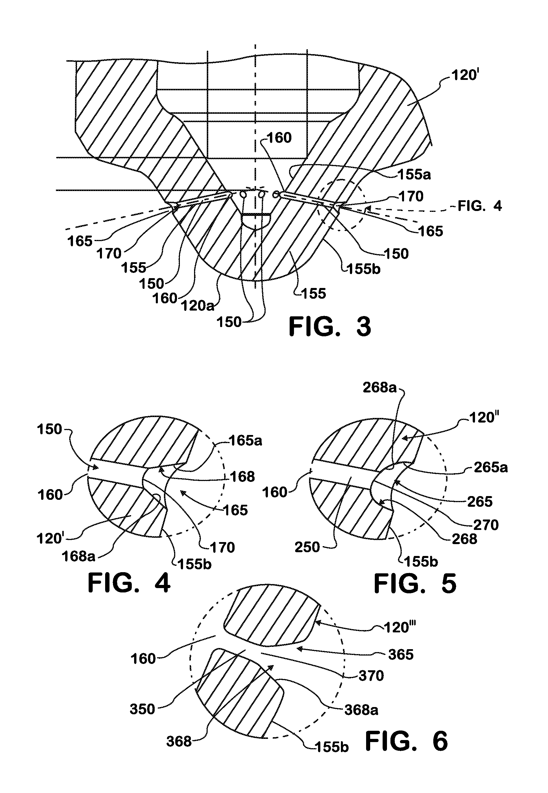
[0029]FIG. 3 illustrates an enlarged section of the tip portion of a modified needle housing 120′ according to a first embodiment of the invention. The needle housing 120′ includes a surrounding wall 155 that has nozzle holes 150 therethrough that are spaced at a pre-determined distance a...


PUM


Abstract

The present invention modifies the outlet holes of a fuel injector for injecting fuel into a cylinder of an internal combustion engine. In the present invention, the outside opening of the outlet holes are modified in a manner that increases the outside opening, making the outside opening larger than the inside opening and creating an intermediate opening, which is recessed with the needle housing.

Description

FIELD OF THE INVENTION[0001]This invention relates to internal combustion engines, including but not limited to needle housings for fuel injectors for use with internal combustion engines.BACKGROUND OF THE INVENTION[0002]Internal combustion engines include crankcases having a plurality of cylinders. The cylinders contain pistons whose reciprocating motion due to combustion events may be transferred through a crankshaft to yield a torque output of the engine. Often, engine crankcases are made of cast metal, and include passages integrally formed therein for the transfer of various fluids from one location of the engine to another. Fluids typically transferred through passages in an engine include coolant, air, fuel, oil, and so forth.[0003]The combustion events within engine cylinders are the result of combustion of a combustible mixture of oxygen and fuel. In modern engines, fuel is injected directly into the cylinder by a fuel injector that is operably associated with each cylinder...

Claims


Application Information

Patent Timeline
Patent Type & Authority Applications(United States)
IPC IPC(8): F02B43/00B05B1/30F02M25/07
CPCF02M57/025F02M61/184F02M61/1833
Inventor SIUCHTA, GRZEGORZMALHOTRA, RAKESH
Owner INT ENGINE INTPROP CO LLC
Why Eureka
Try Eureka