Fuel injector nozzle atomizer having individual passages for inward directed accelerated cross-flow

a fuel injector and atomizer technology, which is applied in the direction of fuel injection apparatus, fuel feed system, spraying apparatus, etc., can solve the problems of increasing the spray atomization level, reducing the velocity of the fuel stream, and inability to achieve the effect of reducing the number of components

Inactive Publication Date: 2006-08-22
DELPHI TECH INC
View PDF10 Cites 22 Cited by
  • Summary
  • Abstract
  • Description
  • Claims
  • Application Information

AI Technical Summary

Benefits of technology

[0007]Briefly described, a director plate system defining a multiple hole plain orifice atomizer for a fuel injector in accordance with the invention include flow channels for directing the fuel stream radially inward toward the discharge holes. The flow channels are tapered inwardly, in the direction of flow, to accelerate the fuel stream. In an alternate embodiment, a swirl element, for imparting tangential velocities or eddies to a plurality of individual fuel streams, is combined with the radially inward directed flow channels. The system in accordance with the invention is readily adaptable to provide various fuel spray patterns. The director plate system may be provided as individual plates in a stack or may be combined with each other and / or the valve seat in a variety of plate configurations to simplify the number of components.

Problems solved by technology

A drawback to this configuration is that other spray patterns, which may be more desirable in applications where precise placement of the fuel spray is needed, cannot be achieved.
The abrupt turn made by the fuel after passing by the seat increases the instability of the individual fuel streams exiting the director plate holes, thereby increasing the level of spray atomization.
Thus, while various spray patterns can be achieved by varying the discharge hole pattern in the director plate, a drawback to this configuration is that the velocity of the fuel stream decreases as it flows radially outward through the director plate channels.

Method used


Image

  • Fuel injector nozzle atomizer having individual passages for inward directed accelerated cross-flow
  • Fuel injector nozzle atomizer having individual passages for inward directed accelerated cross-flow
  • Fuel injector nozzle atomizer having individual passages for inward directed accelerated cross-flow

Examples


embodiments 26a and 26

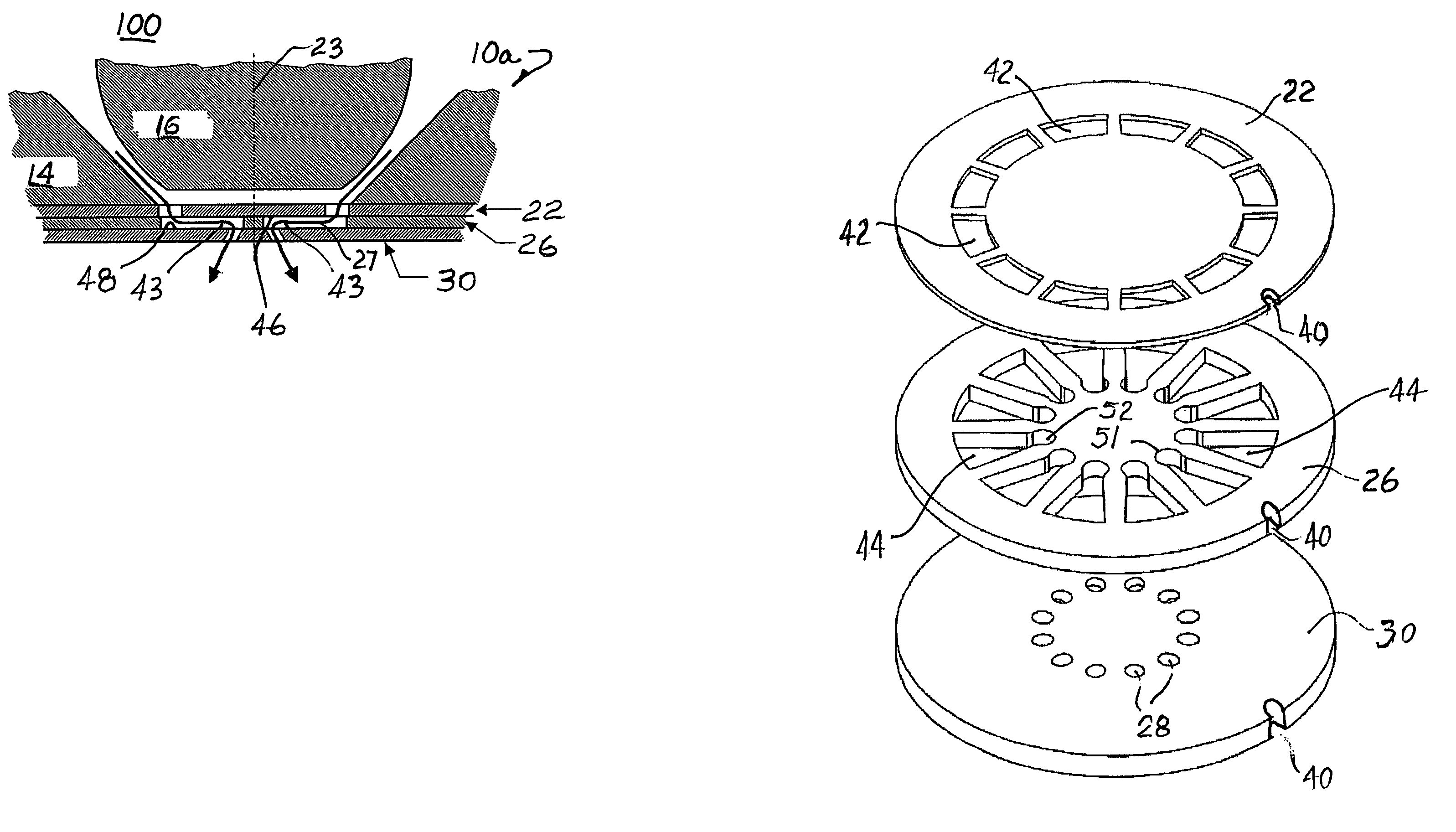
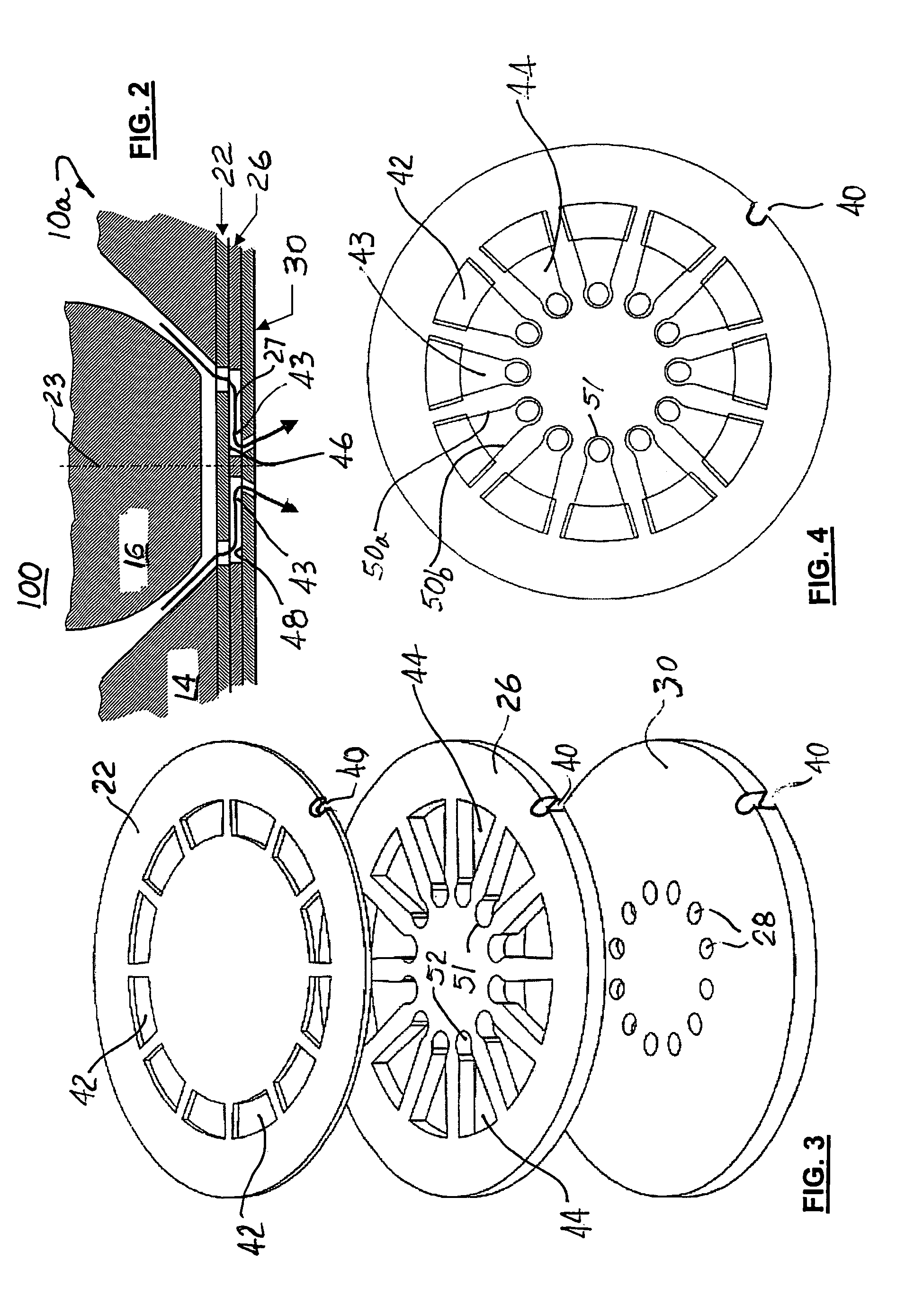
[0023]Alternate embodiments 26a and 26′a of intermediate plate 26 and top plate 26′ are shown in FIGS. 8 and 9, respectively. These embodiments permit the fuel spray pattern to be varied from that of the embodiments shown in FIGS. 5 through 7. In these embodiments, inner ends 51 of alternating cross channels 44 are provided with channel openings 52 positioned at varied radial distances from axis 23. In the embodiment shown, every third opening is positioned at a lesser radial distance from axis 23 than the other two channel openings. Of course, any pattern of varied radial distances may be used within the scope of the invention to achieve a desired fuel spray pattern. Channel openings 52 align with respective discharge holes 28 in director plate 30′.

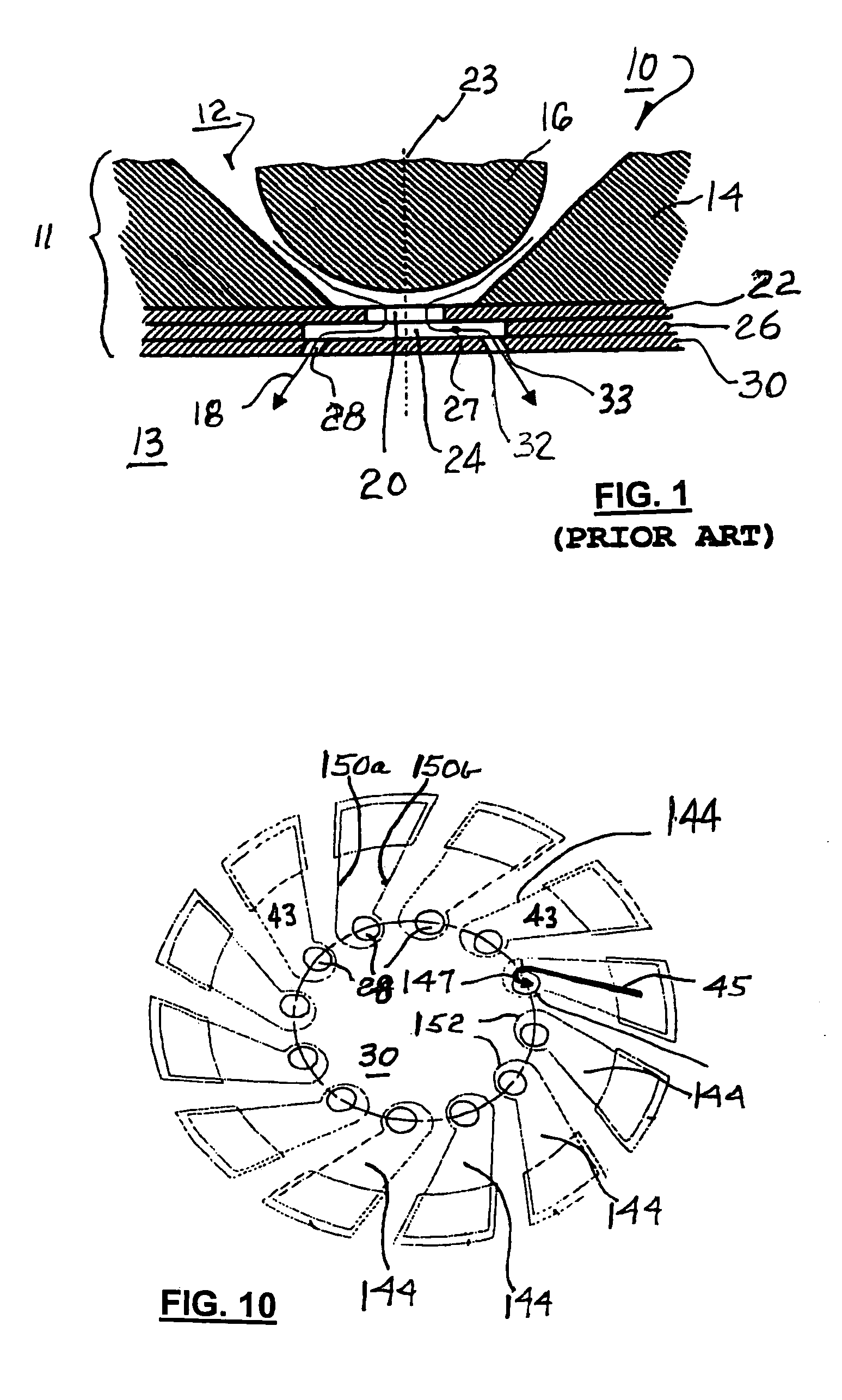
[0024]A swirl feature may be added to the cross flow feature in accordance with the invention. As shown in FIG. 10, each sidewall 150a,150b of swirl channel 144 is non-radial such that a net rotational motion (counterclockwise in the exa...


PUM


Abstract

A director plate system for a fuel injector for use in an internal combustion engine. The system includes flow channels for directing the fuel stream radially inward toward the discharge holes. The cross-sectional area of the flow channels diminish inwardly, in the direction of flow, to accelerate the fuel stream. A swirl element, for imparting tangential velocities or eddies to a plurality of individual fuel streams, can be combined with the radially inward directed flow channels. The director plate system may be provided as individual plates in a stack or may be combined with each other and / or the valve seat in a variety of plate configurations to simplify the number of components.

Description

TECHNICAL FIELD[0001]The present invention relates to internal combustion engines; more particularly, to fuel injectors for use in internal combustion engines; and most particularly, to a fuel injector having a multiple nozzle atomizer with individual passages for generating accelerated cross-flow in an inward direction.BACKGROUND OF THE INVENTION[0002]Fuel injectors for internal combustion engines are well known. Such devices are solenoid-driven valves employed for metering fuel in timed pulses from a high-pressure source such as a fuel rail into either the air intake manifold entrance ports for the individual engine cylinders (“port injection”) or directly into the firing chambers (“direct injection”). In a direct injection system, to achieve high-quality combustion and high fuel efficiency, it is important that the injected fuel be vaporized virtually instantaneously as it exits the injector tip, preferably without striking the walls of the engine cylinder or the top of the pisto...

Claims


Application Information

Patent Timeline
Patent Type & Authority Patents(United States)
IPC IPC(8): F02M61/00F02M61/16F02M61/18
CPCF02M61/186
Inventor SCHNEIDER, MICHAEL
Owner DELPHI TECH INC
Why Eureka
Try Eureka