Fuel injector with premix pilot nozzle

a fuel injector and pilot nozzle technology, which is applied in the direction of machines/engines, mechanical equipment, lighting and heating apparatus, etc., can solve the problems of increasing emissions, unstable operation of gas turbine engines, and performance of gas turbine engines

Active Publication Date: 2015-06-11
GENERAL ELECTRIC CO
View PDF3 Cites 22 Cited by
  • Summary
  • Abstract
  • Description
  • Claims
  • Application Information

AI Technical Summary

Benefits of technology

[0009]One embodiment of the fuel injector with premix pilot nozzle of the present invention includes an apparatus for injecting premixed fuel and air from a plurality of premix passages formed in a premix pilot nozzle at the downstream end of a center body of the injector and into the combustion zone of a gas turbine. The premix pilot nozzle may be supplied with forced air from an active air supply or with passive air supplied through curtain air holes in a conventional swozzle disposed upstream from the premix pilot nozzle. The premix pilot nozzle may be supplied with passive air suppl

Problems solved by technology

However, there is a trade-off in performance of the gas turbine engine.
For as the ratio of fuel to air that is combusted is lowered, there is an increased tendency of the pilot flame of the injector to burn out and thus render unstable the operation of the gas turbine engine.
So-called Lean Blow Out (LBO) ev

Method used


Image

  • Fuel injector with premix pilot nozzle
  • Fuel injector with premix pilot nozzle
  • Fuel injector with premix pilot nozzle

Examples


Embodiment Construction

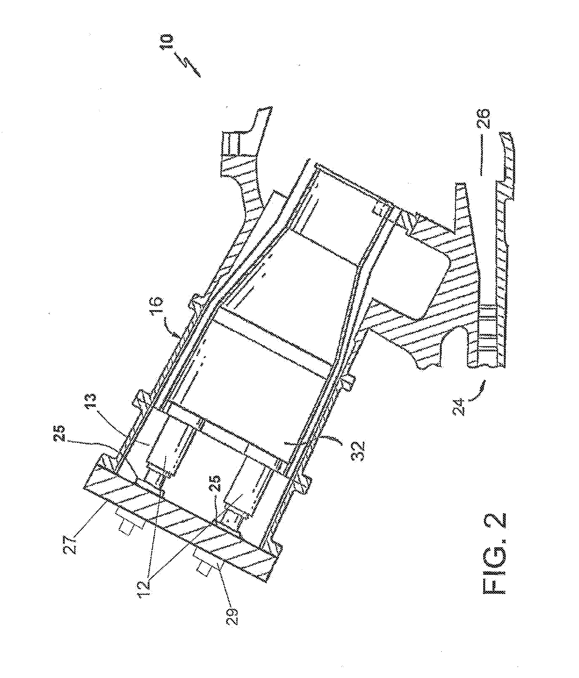
[0028]Reference will now be made in detail to present embodiments of the invention, one or more examples of which are illustrated in the accompanying drawings. The detailed description uses numerical and letter designations to refer to features in the drawings. Like or similar designations in the drawings and description have been used to refer to like or similar parts of the invention.

[0029]Each example is provided by way of explanation of the invention, not limitation of the invention. In fact, it will be apparent to those skilled in the art that modifications and variations can be made in the present invention without departing from the scope or spirit thereof For instance, features illustrated or described as part of one embodiment may be used on another embodiment to yield a still further embodiment. Thus, it is intended that the present invention covers such modifications and variations as come within the scope of the appended claims and their equivalents.

[0030]It is to be und...


PUM


Abstract

An apparatus for injecting premixed fuel and air through a center body and into the combustion zone of a gas turbine includes a fuel injector nozzle with a premix pilot nozzle having a plurality of premix passages in fluid communication with an air supply and a fuel supply that premixes air and fuel within the premix passages. The apparatus has either an active or passive fuel feed control. Fuel can be fed to the apparatus either conventionally or as a breech load circuit integrated into the oil cartridge. Fuel can be supplied passively via a fuel channel connecting the swozzle fuel plenum to the premix passages. Alternatively, fuel can be injected from the oil cartridge into the premix passages.

Description

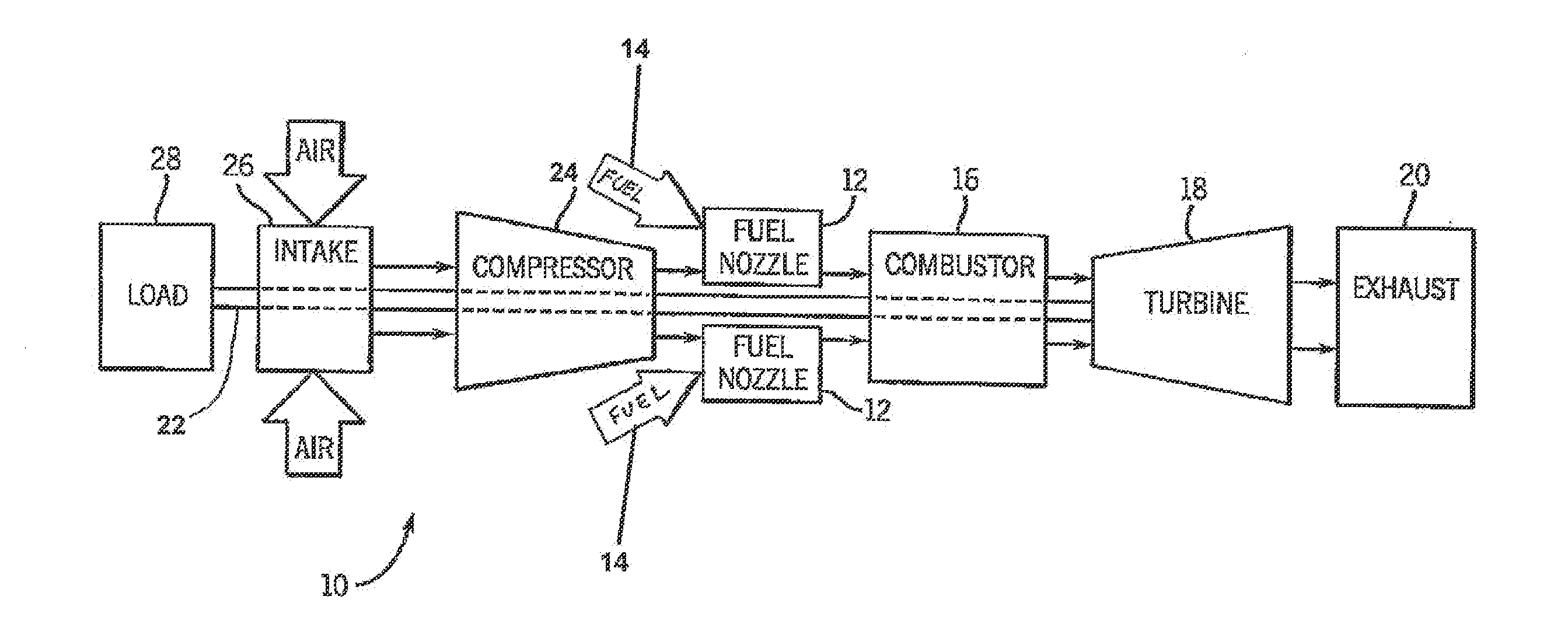
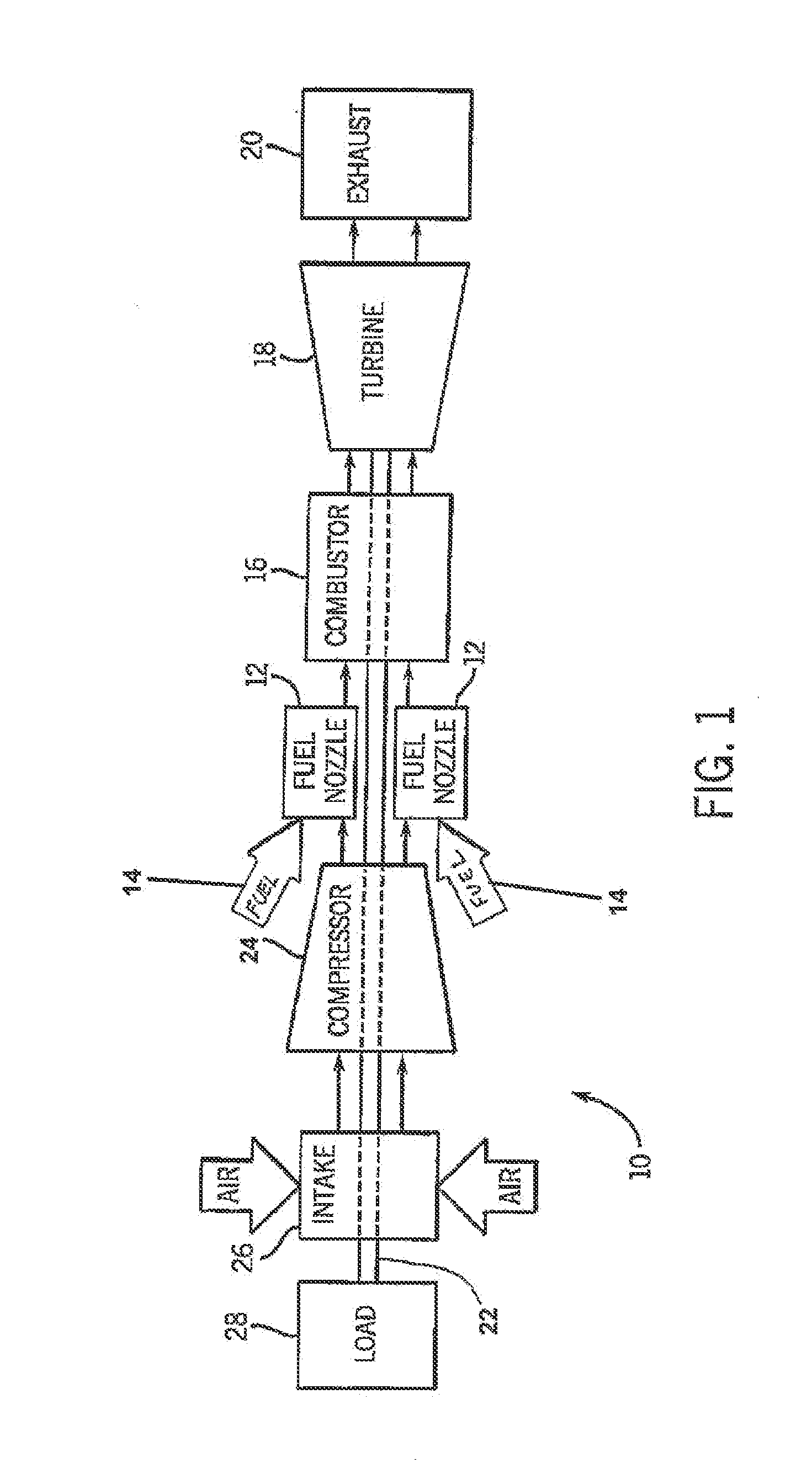
FIELD OF THE INVENTION[0001]The present invention generally involves a gas turbine engine that combusts a hydrocarbon fuel mixed with air to generate a high temperature gas stream that drives turbine blades to rotate a shaft attached to the blades and more particularly to the engine's fuel injector having a pilot nozzle that premixes fuel and air while achieving lower nitrogen oxides.BACKGROUND OF THE INVENTION[0002]Gas turbine engines are widely used to generate power for numerous applications. A conventional gas turbine engine includes a compressor, a combustor, and a turbine. In a typical gas turbine engine, the compressor provides compressed air to the combustor. The air entering the combustor is mixed with fuel and combusted. Hot gases of combustion are exhausted from the combustor and flow into the blades of the turbine so as to rotate the shaft of the turbine connected to the blades. Some of that mechanical energy of the rotating shaft drives the compressor and / or other mecha...

Claims


Application Information

Patent Timeline
IPC IPC(8): F23R3/28
CPCF23R3/286F02C7/222F05D2220/32F23R3/343F23R2900/03343
Inventor BERRY, JONATHAN DWIGHTHUGHES, MICHAEL JOHNEDWARDS, KARA JOHNSTON
Owner GENERAL ELECTRIC CO
Why Eureka
Try Eureka