Fuel injector nozzle for an internal combustion engine

a fuel injector and internal combustion engine technology, which is applied in the direction of fuel injection apparatus, combustion engine, charge feed system, etc., can solve the problems of increasing the localized high temperature regions of the combustion chamber, noxious and noxious,

Inactive Publication Date: 2006-04-25
CATERPILLAR INC
View PDF40 Cites 22 Cited by
  • Summary
  • Abstract
  • Description
  • Claims
  • Application Information

AI Technical Summary

Problems solved by technology

Such a narrow range of diffusion of fuel plumes limits the mixing of the fuel with the air, thus increasing the localized high temperature regions in the combustion chamber and thereby producing unwanted smoke and NOx.

Method used


Image

  • Fuel injector nozzle for an internal combustion engine
  • Fuel injector nozzle for an internal combustion engine
  • Fuel injector nozzle for an internal combustion engine

Examples


Embodiment Construction

[0019]Reference will now be made in detail to the drawings. Wherever possible, the same reference numbers will be used throughout the drawings to refer to the same or like parts.

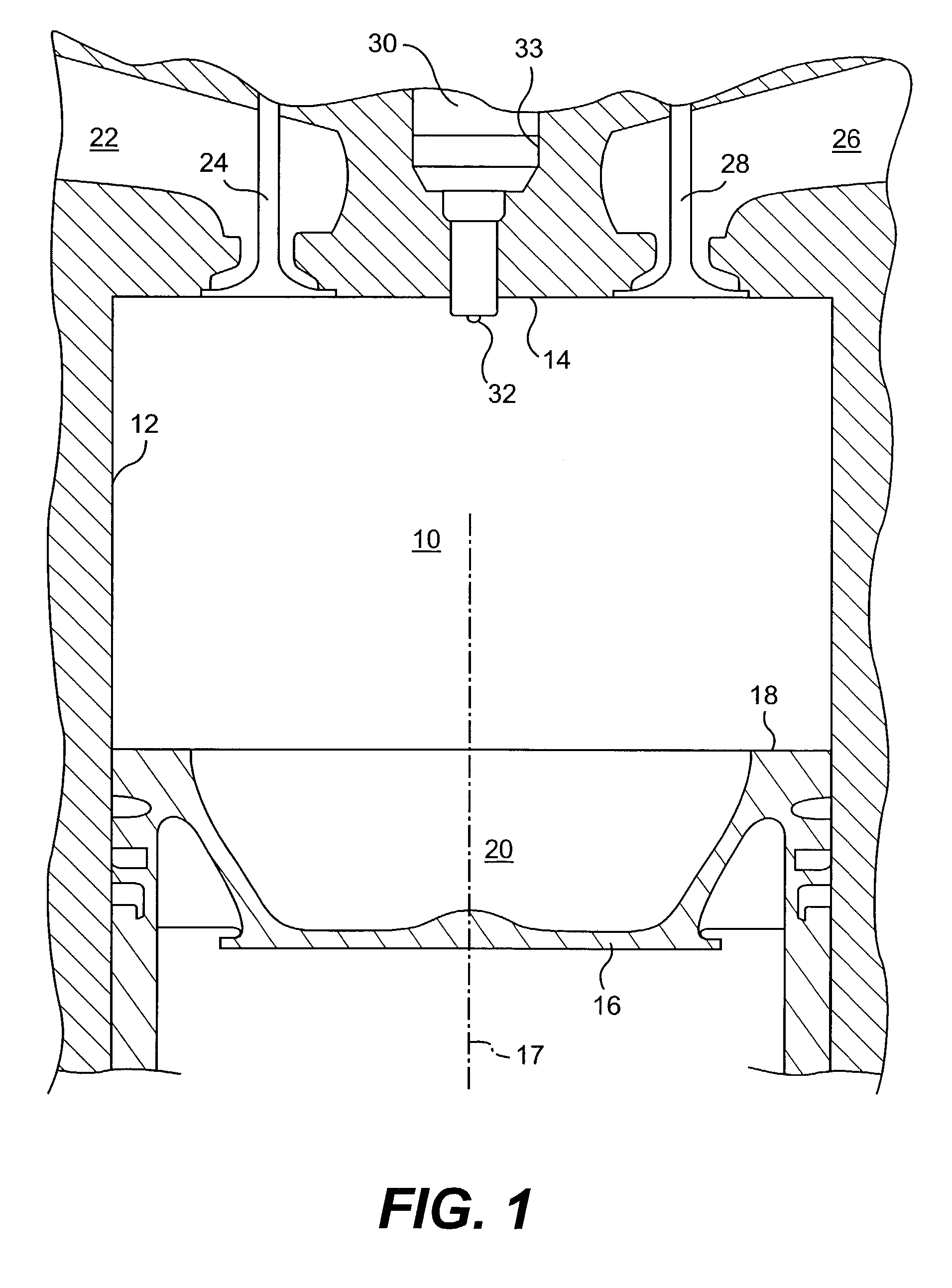
[0020]FIG. 1 illustrates a combustion chamber assembly of an internal combustion engine including a combustion chamber 10. Such an engine may include, for example, a four stroke diesel fuel powered engine. The combustion chamber 10 is formed by a cylinder sidewall 12, a cylinder end wall 14, and a reciprocating piston 16, and includes a combustion chamber longitudinal axis 17. The piston 16 may have a top surface 18 forming a piston crater 20. As is conventional in the art, an intake port 22, intake valve 24, exhaust port 26, and exhaust valve 28 may be located about the cylinder end wall 14.

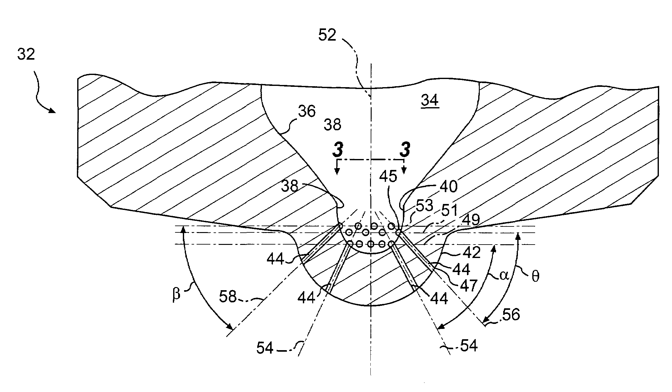
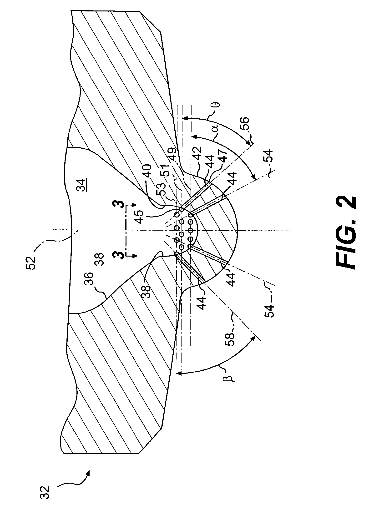
[0021]A fuel injector 30 may include a nozzle tip 32 extending directly into the combustion chamber 10 through an opening 33 in the cylinder end wall 14. The fuel injector 30 may be concentric or parallel with the longit...


PUM


Abstract

A direct injection fuel injector includes a nozzle tip having a plurality of passages allowing fluid communication between an inner nozzle tip surface portion and an outer nozzle tip surface portion and directly into a combustion chamber of an internal combustion engine. A first group of the passages have inner surface apertures located substantially in a first common plane. A second group of the passages have inner surface apertures located substantially in at least a second common plane substantially parallel to the first common plane. The second group has more passages than the first group.

Description

U.S. GOVERNMENT RIGHTS[0001]The U.S. Government has a paid-up license in this invention and the right in limited circumstances to require the patent owner to license others on reasonable terms as provided for by the terms of Contract Nos. DE-FC05-00OR22806 and DE-FC05-97OR22605 awarded by the Department of Energy.TECHNICAL FIELD[0002]This invention relates generally to fuel systems for internal combustion engines, and more particularly to nozzle configurations of fuel injectors of fuel systems of internal combustion engines.BACKGROUND[0003]The conventional combustion process in diesel engines is initiated by the direct injection of fuel into a combustion chamber containing compressed air. The fuel is almost instantaneously ignited upon injection into the highly compressed combustion chamber, and thus produces a diffusion flame or flame front extending along the plumes of the injected fuel. The fuel is directly injected into the combustion chamber by a fuel injector having a nozzle t...

Claims


Application Information

Patent Timeline
Patent Type & Authority Patents(United States)
IPC IPC(8): F02B3/00F02B1/12F02M61/18
CPCF02M61/1826F02M61/182F02B1/12
Inventor CAVANAGH, MARK S.URVEN, JR., ROGER L.LAWRENCE, KEITH E.
Owner CATERPILLAR INC
Why Eureka
Try Eureka