Stackable yard cart

a cart and storage technology, applied in the field of storage carts, can solve the problems of requiring a great deal of space to store yard equipment, optimal choices, and difficulty in storage and transportation of yard equipment, and achieve the effect of low cost and high quality

Inactive Publication Date: 2005-02-01
AMES TRUE TEMPER
View PDF12 Cites 49 Cited by
  • Summary
  • Abstract
  • Description
  • Claims
  • Application Information

AI Technical Summary

Benefits of technology

A yard cart according to the present invention overcomes at least some of the above noted and other deficiencies. According to one aspect of the present invention, a stackable cart includes a tray, a handle connected to the tray, and a plurality of wheels rotatably secured to the tray. The tray is configured to at least partially receive a handle of another cart when the another cart is stacked on the stackable cart. The handle is configured to at least partially receive a plurality of wheels of the another cart when the another cart is stacked on the stackable cart.
According to another aspect of the present invention, a stacked configuration of carts includes first and second carts each including a tray, a handle connected to the tray, and a plurality of wheels rotatably secured to the tray. The second cart is vertically stacked upon the first cart with the second cart oriented in an opposed direction to the first cart. The tray of the first cart at least partially receives the handle of the second cart therein to limit movement of the second cart relative to the first cart. The handle of the first cart at least partially receives the plurality of wheels of the second cart therein to limit movement of the second cart relative to the first car

Problems solved by technology

Yard equipment is typically difficult to store and difficult to transport.
Businesses or individuals that require a significant number of wheelbarrows or carts, for example, require a great deal of space to store this equipment.
Furth

Method used


Image

  • Stackable yard cart
  • Stackable yard cart
  • Stackable yard cart

Examples


Embodiment Construction

A preferred embodiment of the present invention and its advantages are best understood by referring to FIGS. 1 to 5 wherein like reference numerals are used for like and corresponding parts of the various figures. It will be apparent to those skilled in the art, that is, to those who have knowledge or experience in this area of technology, that many uses and design variations are possible for the improved yard carts disclosed herein.

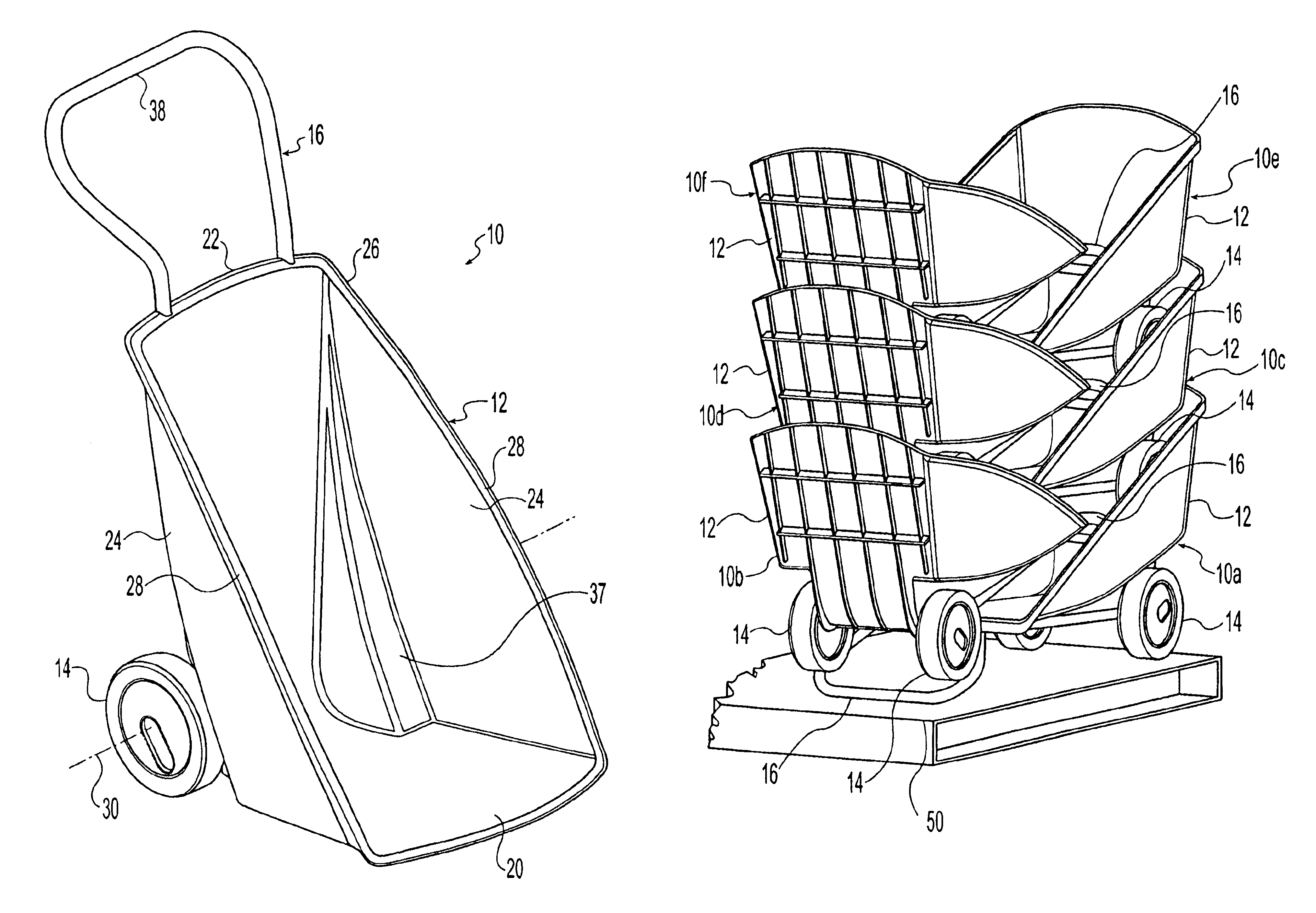
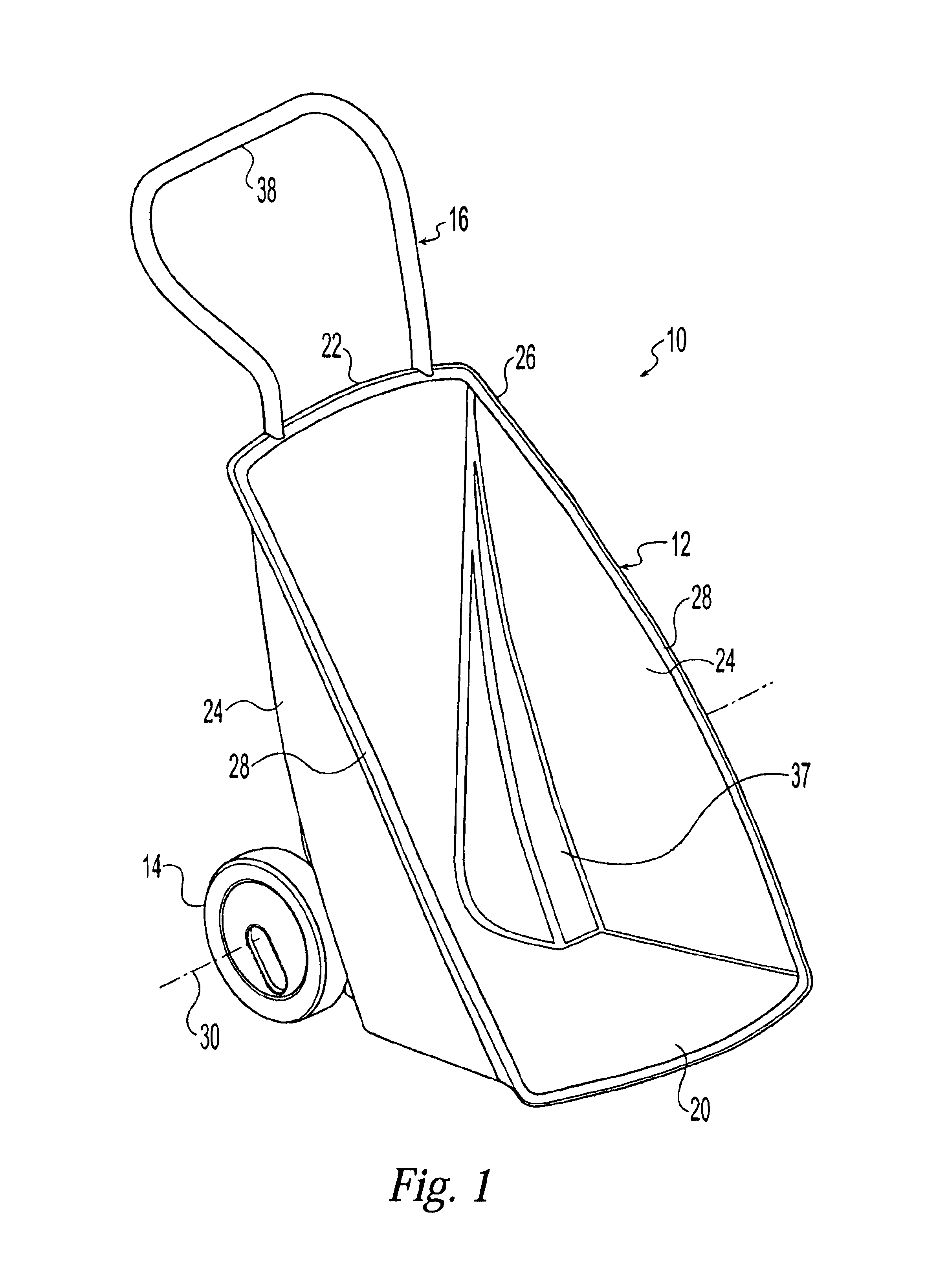
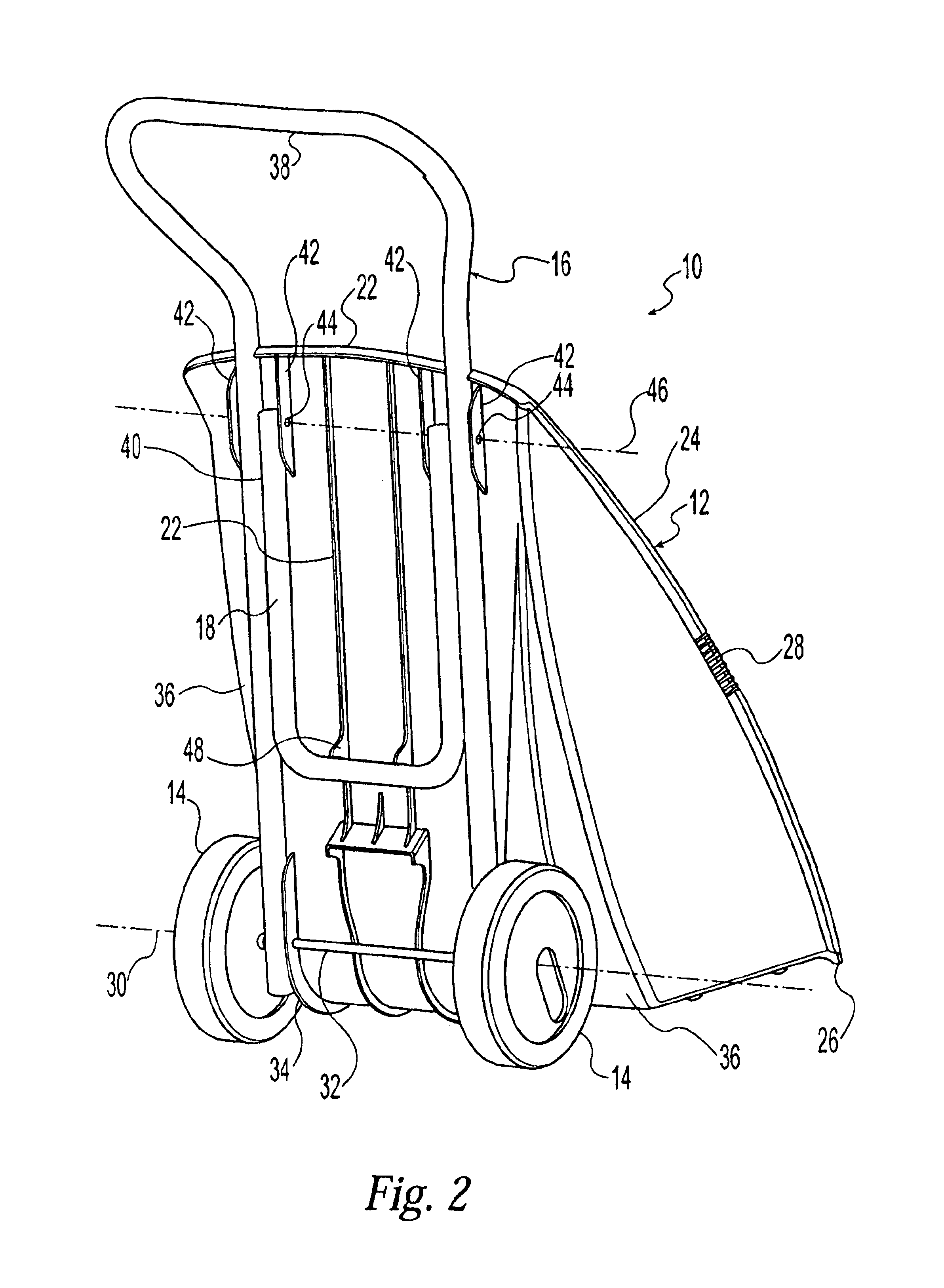
Referring now to the drawings, FIGS. 1 to 3 show a yard cart 10 according to a first embodiment of the present invention. Generally, the yard cart 100 includes a tray 12, a pair of wheels 14, a handle 16, and a stand 18. The tray 12 may be made of any suitable material such as, for example, plastic, metal or any other appropriate materials.

The illustrated tray 12 includes a generally planar bottom wall 20, a generally planar back wall 22 upwardly extending from a rear edge of the bottom wall 20, and a pair of generally planar side walls 24 upwardly exten...


PUM


Abstract

A stackable cart upon which another cart can be stacked thereon includes a tray, a handle connected to the tray, and a plurality of wheels rotatably secured to the tray. The tray is configured to at least partially receive a handle of the another cart when the another cart is stacked on the stackable cart. The handle is configured to at least partially receive a plurality of wheels of the another cart when the another cart is stacked on the stackable cart. A plurality of the carts can be stored vertically with the carts oriented in alternating opposed directions. The carts are preferably nested together in a compact manner. In some disclosed embodiments the handle is a handle movable between an extended position and a retracted position and/or the cart includes a stand movable between a stowed position and an extended position.

Description

STATEMENT REGARDING FEDERALLY SPONSORED RESEARCHNot ApplicableREFERENCE TO MICROFICHE APPENDIXNot ApplicableFIELD OF THE INVENTIONThe present invention generally relates to yard equipment and, more particularly, to a stackable yard cart.BACKGROUND OF THE INVENTIONYard equipment is typically difficult to store and difficult to transport. Businesses or individuals that require a significant number of wheelbarrows or carts, for example, require a great deal of space to store this equipment. Further, should it be necessary to transport this equipment to a work location, it may be necessary to decide between not taking all of the available equipment or making multiple trips to move the equipment; both are not optimal choices. Accordingly, there is a need in the art for an improved yard cart.SUMMARY OF THE INVENTIONA yard cart according to the present invention overcomes at least some of the above noted and other deficiencies. According to one aspect of the present invention, a stackable ...

Claims


Application Information

Patent Timeline
IPC IPC(8): B62B1/00B62B1/18B62B3/14B62B3/16B62B5/06B62B5/00
CPCB62B1/006B62B3/16B62B1/18B62B1/008B62B2501/065B62B5/065
Inventor PANASEWICZ, DALE A.FUTO, DENNISKALMAN, JEFFREYPASSERELL, RENARD J.
Owner AMES TRUE TEMPER
Why Eureka
Try Eureka