

Power door latch assembly
a technology of latch assembly and door latch, which is applied in the direction of carpet fasteners, electrical locking circuits, and lock applications, etc., can solve the problems of insufficient internal energy of the door latch, inability to completely close and latch manually latching the vehicle door on current model vehicles, and complex rotary actuators
- Summary
- Abstract
- Description
- Claims
- Application Information
AI Technical Summary
Benefits of technology
Problems solved by technology
Method used
Image

Examples
Embodiment Construction
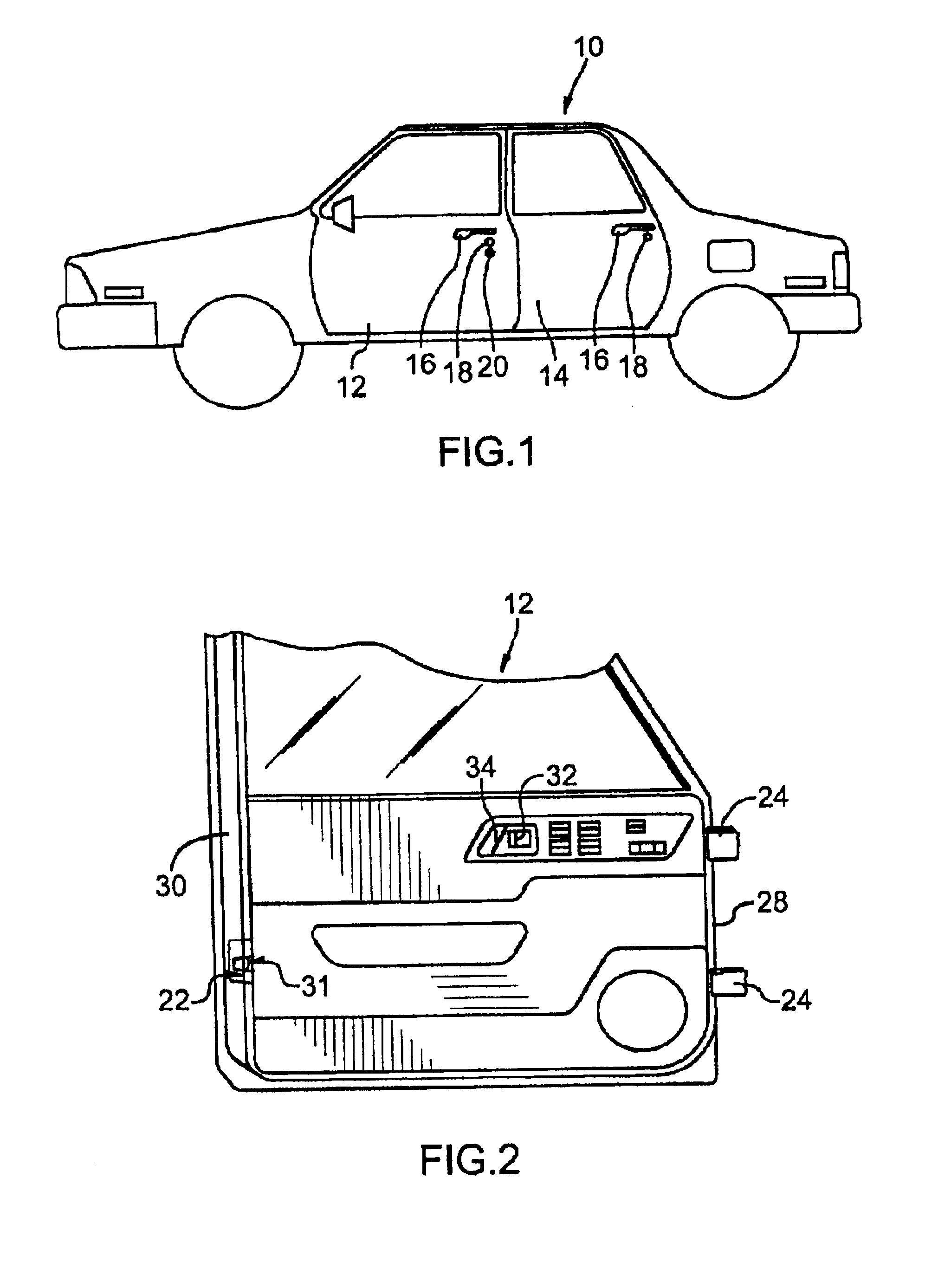
FIG. 1 shows a left side elevational view of the exterior of a conventional motor vehicle that has a front door 12 and a back door 14. Each door 12, 14 has an exterior handle 16 and a door latch opening button 18. The front door 12 has a conventional key-operated lock cylinder to lock and unlock the door 12.
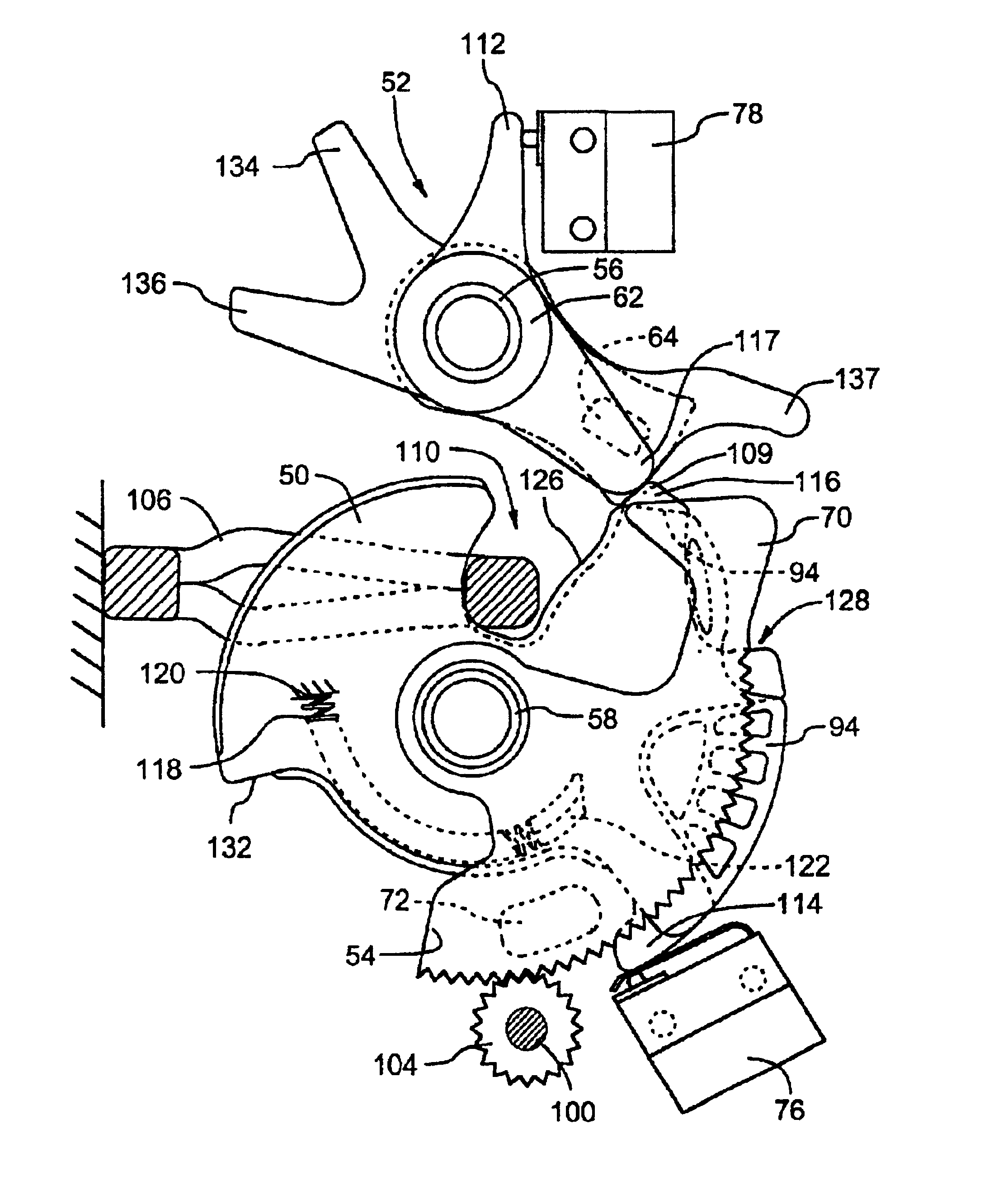
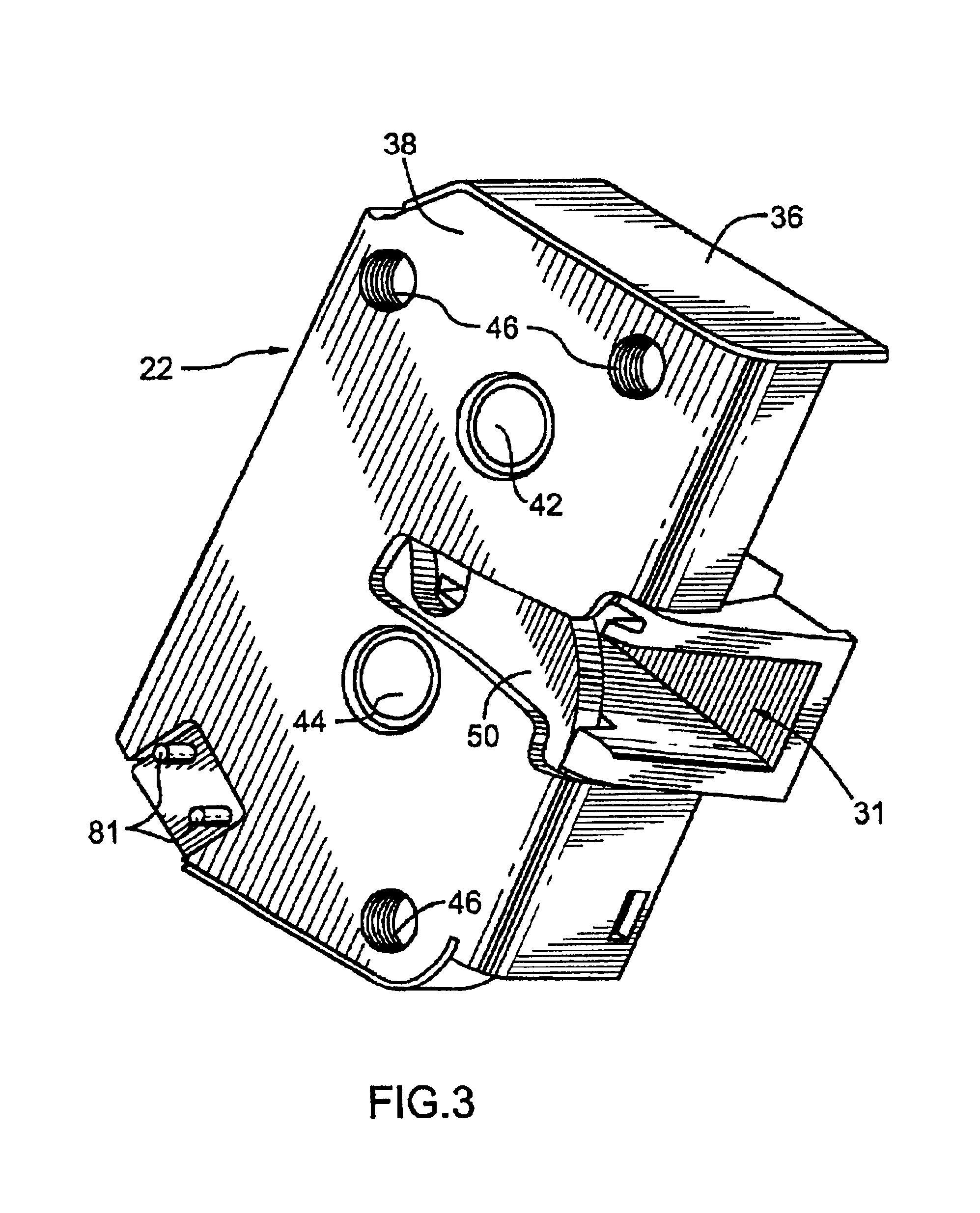
A power operated door latch assembly 22 constructed according to the principles of the present invention is mounted on each door of the vehicle 10 for the power assisted latching and unlatching of each door.
FIG. 2 shows an isolated view of the inside of the front door 12. Two hinges 24 are secured to a first inner edge 28 of the door 12 to pivotally mount the door 12 to a door frame on the vehicle 10 in a conventional manner so the door can be moved between open and closed positions. A power operated door latch assembly 22 is mounted on a second outer edge 30 of the door. The door 12 has an interior door release switch 32 to unlatch the door latch assembly 22 with power assistanc...
PUM
 Abstract
Description
Claims
Application Information