Coaxial cable connector with integral grip bushing for cables of varying thickness

Active Publication Date: 2005-02-01
IDEAL IND INC
View PDF36 Cites 223 Cited by
  • Summary
  • Abstract
  • Description
  • Claims
  • Application Information

AI Technical Summary

Benefits of technology

A single size of connector of the present invention can be used with common RG6 and Tri Shield RG6 cable, and also with Quad Shield

Problems solved by technology

Crimping tools tend to wear out with repeated use, and crimping does not provide a satisfactory seal.
A problem with this connector is that it can be awkward to break the compression sleeve away from the connector and then thread it onto the cable, particularly when used in field installations where there may be adverse weather conditions.
The compression sleeve can as well be inadvertently threaded onto the cable backwards, and it can also be dropped and lost.
While this grip bushing cable connector has many advantages, it does not lend

Method used


Image

  • Coaxial cable connector with integral grip bushing for cables of varying thickness
  • Coaxial cable connector with integral grip bushing for cables of varying thickness

Examples


Embodiment Construction

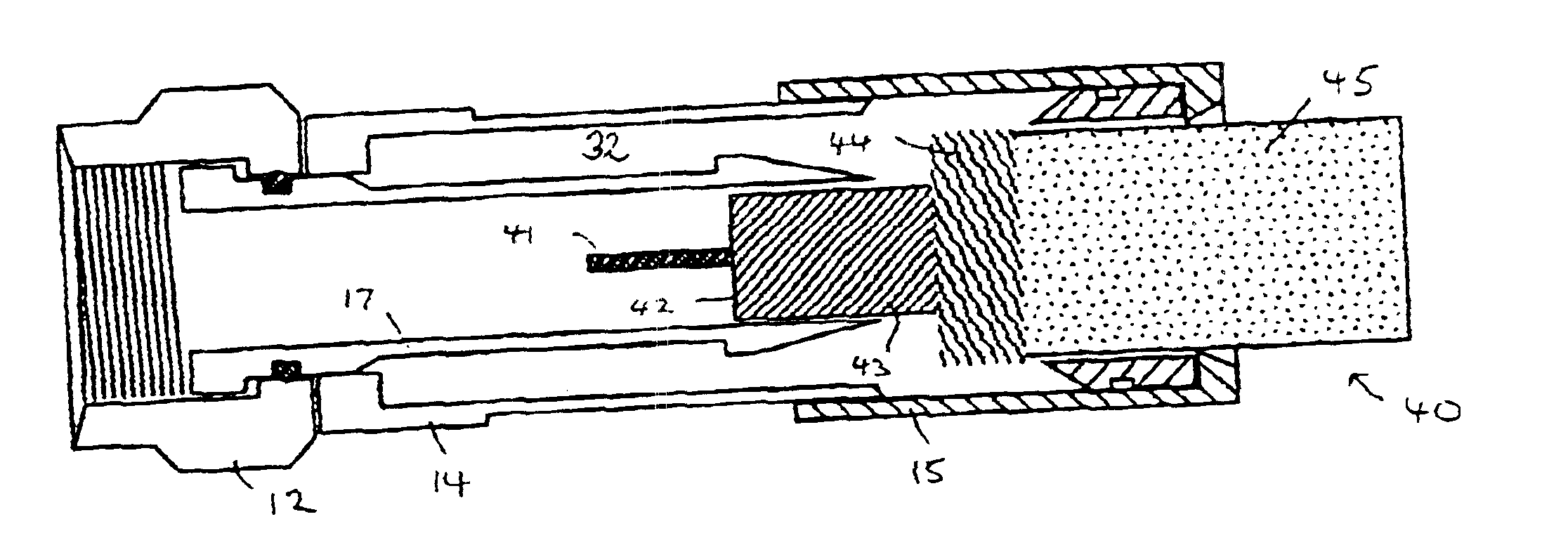
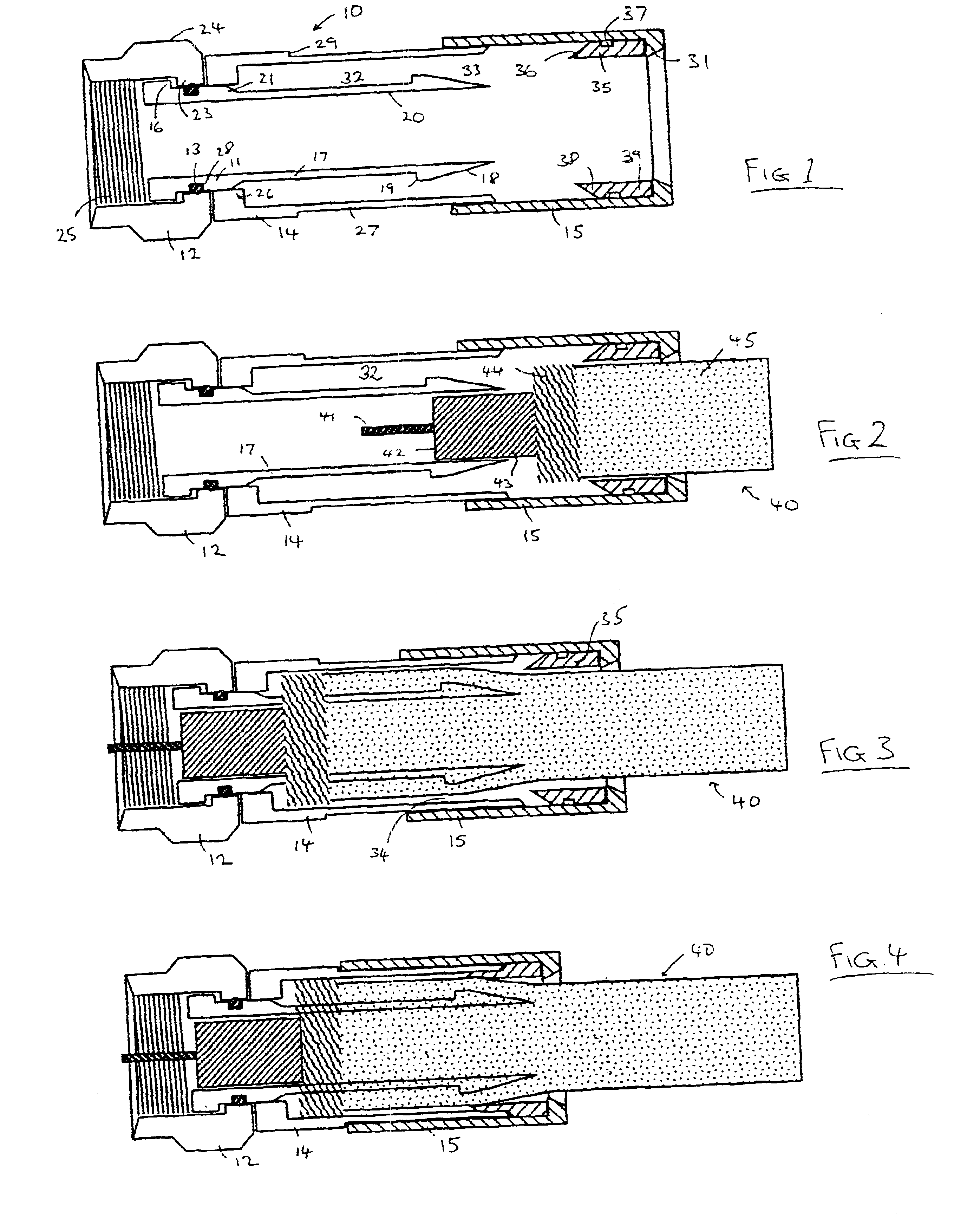
In the drawings, the coaxial cable connector is denoted generally by reference number 10. The cable is denoted by reference number 40 and is of a standard configuration comprising a central conductor 41, a dielectric insulator 42 with a foil cover 43, a braided shield 44 and a plastic jacket 45.

The connector 10 comprises a mandril 11, a nut member 12, an O-ring 13, a retainer 14 and a bushing 15 having an internal collar 35. The O-ring 13 is made of a compressible, elastomeric material, such as rubber or plastic. The mandril 11, nut member 12, retainer 14, and bushing 15 are all made of a rigid material, preferably metallic, such as brass. The collar 35 of the bushing 15 is made of a deformable material such as Delrin®, an acetal resin available from E.I. Dupont de Nemours and Company.

The mandril 11 is generally cylindrical having an enlarged base with a sleeve 17 extending therefrom. A flange 16 projects outwardly from the end of the enlarged base of the mandril 11. The sleeve 17 h...


PUM


Abstract

A connector is provided for interconnecting a coaxial cable to an electrical device. The connector has an internal body and an external body which are assembled together, and which can be activated to clamp upon and seal to an inserted coaxial cable without disassembling the external body from the internal body. The external body includes a deformable inner collar that permits the connector to be attached and sealed to cables of varying thickness as are found on common single foil and braid cable, Tri Shield cable and Quad Shield cable.

Description

FIELD OF THE INVENTIONThis invention relates generally to a connector for coaxial cable, such as the type used for cable TV transmission.BACKGROUND OF THE INVENTIONCoaxial cable connectors that require crimping are associated with certain disadvantages. Crimping tools tend to wear out with repeated use, and crimping does not provide a satisfactory seal. A number of crimpless connectors have been developed which attempt to overcome these problems.One type of crimpless connector receives a compression sleeve, which is first broken away from a plastic ring mounted on the connector, and then slid over the cable and finally inserted into the annular cavity between the inner wall of the connector and the jacket of the cable. A tool is used to push the compression sleeve fully into the connector with a snap engagement.A problem with this connector is that it can be awkward to break the compression sleeve away from the connector and then thread it onto the cable, particularly when used in f...

Claims


Application Information

Patent Timeline
IPC IPC(8): H01R9/05
CPCH01R9/0521
Inventor STIRLING, ALBERT
Owner IDEAL IND INC
Why Eureka
Try Eureka