Information recording medium with index header

a technology of information recording and index header, applied in the field of information recording medium, can solve the problems of affecting recording stability, affecting recording/reproduction stability, and affecting recording/reproduction stability, and achieve the effect of accurate recording and reproduction of information and high recording efficiency

Inactive Publication Date: 2005-02-01
KK TOSHIBA
View PDF14 Cites 71 Cited by
  • Summary
  • Abstract
  • Description
  • Claims
  • Application Information

AI Technical Summary

Benefits of technology

(5) an information reproduction apparatus and method for reproducing data recorded on an information recording medium which has a plurality of recording layers on one surface thereof, and can accurately record and reproduce information on/from all recording layers; and
(6) an information reproduction apparatus and method for re

Problems solved by technology

1. When both recorded and non-recorded areas are present on the front recording layer, since the intensity of recording light which is transmitted through the front recording layer and reaches the back recording layer varies between these areas, inter-recording marks formed on the back recording layer by this recording light become uneven, thus impairing recording stability.
2. When both recorded and non-recorded areas are present on the front recording layer, since the intensity of reproduction light, which is transmitted through the front recording layer, reaches the back recording layer, is reflected by the back recording layer, and is transmitted through the front recording layer again, varies between these areas, errors readily occur in a reproduction signal. Furthermore, since the reflectance of the front recording layer changes, a reproduction signal suffers an offset, thus impairing reproduction stability.
When the two recording layers having such structures are adhered without any constraints, recording/reproduction stability suffers.
This causes considerable format efficiency drop of the DVD-RAM compared to the DVD-ROM.
As a result, problems such as transfer rate drop, difficulty in seamless recording, and the like are posed.
Furthermore, when the training pattern is formed in a recording field, it becomes difficult to specify the position of the training pattern upon recording/

Method used


Image

  • Information recording medium with index header
  • Information recording medium with index header
  • Information recording medium with index header

Examples


first embodiment

the present invention will be described below with reference to the accompanying drawings.

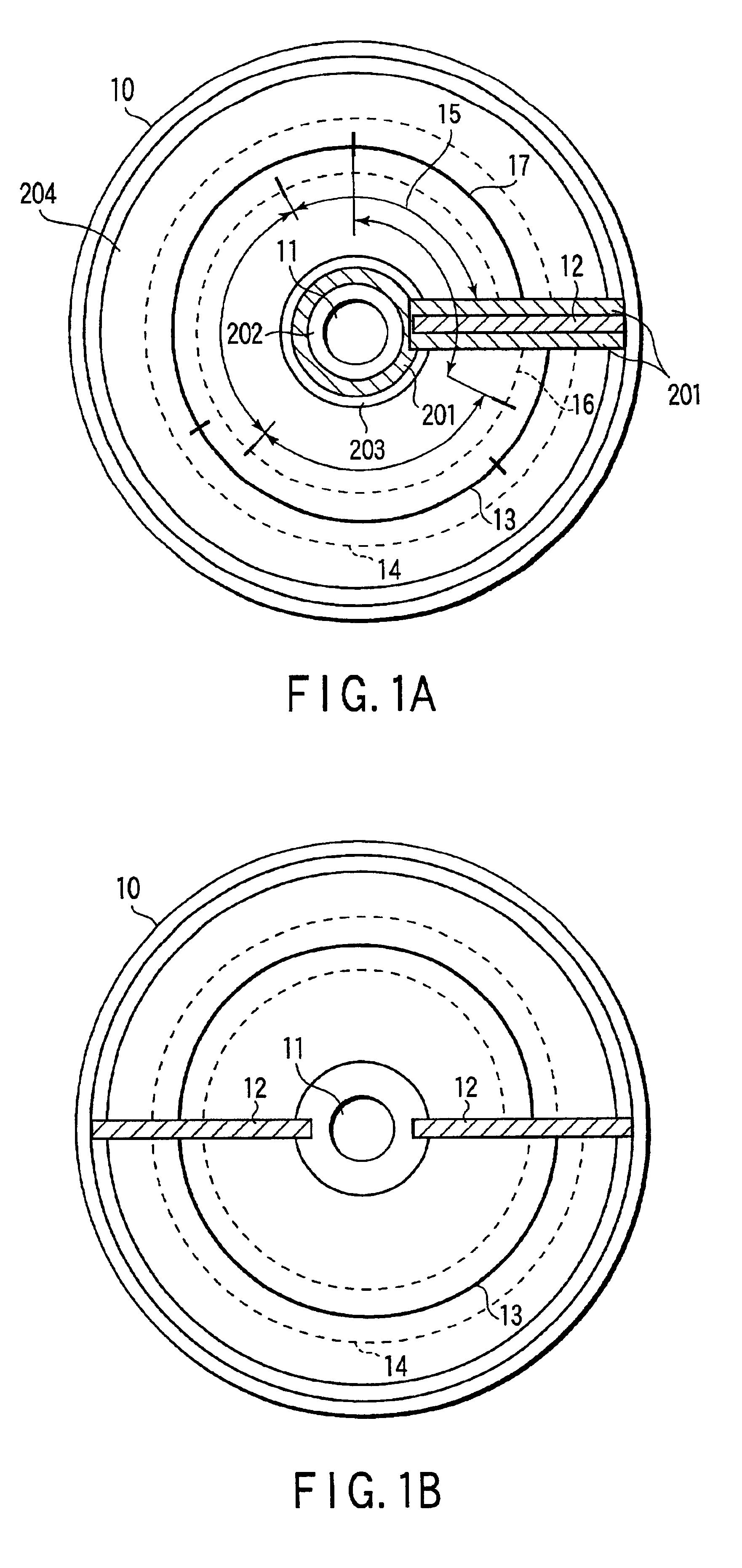
FIG. 1A shows a schematic structure of an optical disk (information recording medium) according to an embodiment of the present invention. An optical disk 10 has a plurality of stacked recording layers. On the optical disk 10, a light beam coming from one surface side records data in a spiral track formed on an arbitrarily selected target recording layer, and reproduces data recorded in the spiral track formed on the target recording layer.

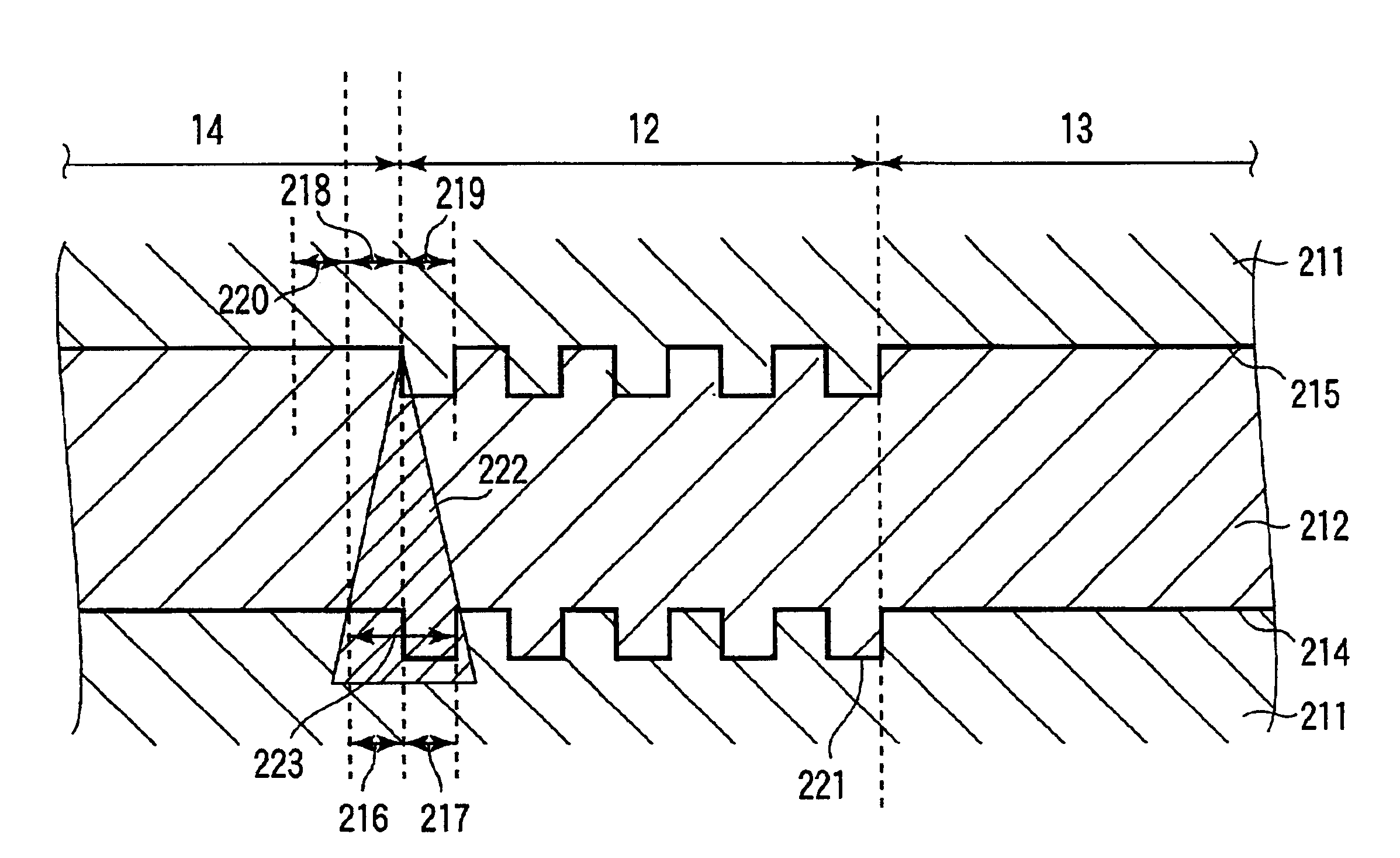
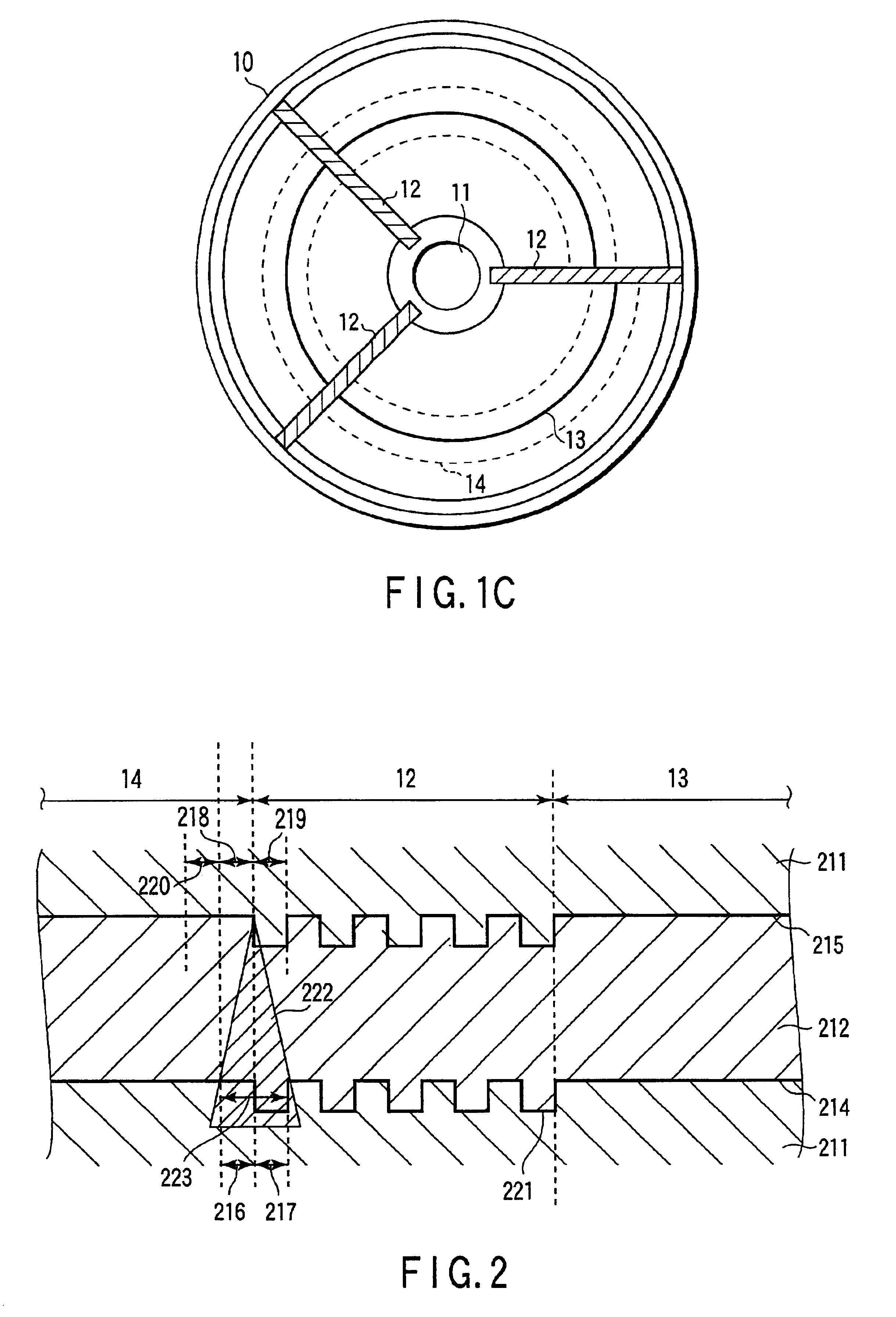
FIG. 2 is a sectional view showing an optical disk having no dummy area 201 taken along a track across an index header. FIG. 3 is a graph showing a change in transmittance of light in a first recording layer 214 when a light beam is scanned along a track while being focused on a second recording layer 215 on the optical disk shown in FIG. 2. FIG. 4 is a sectional view of the optical disk 10 shown in FIG. 1A taken along a track across an index header, and show...

second embodiment

the present invention will be described below with reference to the accompanying drawings.

A recordable optical disk according to an embodiment of the present invention will be described first. FIG. 28 shows the entire optical disk, FIG. 29 shows the track configuration of the optical disk, and FIG. 30 shows an embodiment of the layout of adjustment areas.

As shown in FIG. 28, an optical disk 10 comprises a spiral track (recording track) made up of groove-shaped groove tracks 13. Furthermore, the optical disk 10 comprises index headers 12 which are aligned in the radial direction of the disk to intercept the spiral track, and comprises adjustment areas a 2010 for wobbles on one or both sides of these index headers 12, and adjustment areas b 2020 which are located outside the adjustment areas a 2010 and are used to break up recording fields 15 in unit of sync frames. The trailing end position of the spiral track is adjusted by the adjustment areas.

The spiral track of the optical disk 1...


PUM


Abstract

An information recording medium has a plurality of stacked recording layers. Each recording layer has a spiral track which defines a plurality of rounds, and at least one index header aligned in the radial direction of the disk to partially intercept the spiral track. The index header has address data of each round of the spiral track, which is formed by embossed pits, and some or all of the index headers of the first and second recording layers are laid out to overlap each other when viewed from the predetermined surface.

Description

CROSS-REFERENCE TO RELATED APPLICATIONSThis application is based upon and claims the benefit of priority from the prior Japanese Patent Applications No. 2000-224724, filed Jul. 26, 2000; and No. 2000-324188, filed Oct. 24, 2000, the entire contents of both of which are incorporated herein by reference.BACKGROUND OF THE INVENTIONThe present invention relates to an information recording medium such as an optical disk or the like on / from which data can be recorded / reproduced. The present invention also relates to an information recording apparatus and method for recording information on the information recording medium. Furthermore, the present invention relates to an information reproduction apparatus and method for reproducing information recorded on the information recording medium.As one of information recording media, for example, a phase change type rewritable optical disk is known. When such optical disk is irradiated with a focused light beam, phase change marks are formed on t...

Claims


Application Information

Patent Timeline
IPC IPC(8): G11B27/19G11B27/10G11B27/30G11B27/24G11B20/12G11B7/007G11B20/00G11B20/10
CPCG11B7/007G11B7/00745G11B20/1217G11B27/105G11B27/24G11B27/3027G11B7/00718G11B2220/2575G11B20/00086G11B20/10009G11B20/12G11B20/1258G11B2220/216G11B2220/235G11B2220/2562
Inventor OGAWA, AKIHITOSUGAYA, TOSHIHIRO
Owner KK TOSHIBA
Why Eureka
Try Eureka