Optical information reproducing method and apparatus for performing reproduction compensation

a technology of optical information and reproduction compensation, applied in the direction of digital signal error detection/correction, instruments, recording signal processing, etc., can solve the problems of large possibility of bit droppage, and cannot treat the waveform deviation of a reproduced signal, so as to correctly reproduce recording information

Inactive Publication Date: 2007-03-06
CANON KK
View PDF14 Cites 3 Cited by
  • Summary
  • Abstract
  • Description
  • Claims
  • Application Information

AI Technical Summary

Benefits of technology

[0010]The present invention has been made in view of the above-described conventional problems, and an object of the present invention is to provide an optical information reproducing method and an optical information reproducing apparatus for correcting a waveform deviation generated by the characteristics of a medium, a record and reproduction system, etc., and for being able to correctly reproduce recording information.

Problems solved by technology

However, the above-described method of Japanese Patent Application Laid-Open No. 10-50000 in which only a level changing point is referred cannot treat, for example, a case where an amount of a waveform deviation changes depending on a waveform pattern to the changing point.
Furthermore, the method of compensating a waveform deviation at the time of record that is disclosed in Japanese Patent Application Laid-Open No. 05-197957 has a large possibility of generating bit droppage, etc. by the influence of compensation by a record pulse below the shortest mark length if the shortest mark length is shortened for a high densification.
Therefore, correction by a fixed amount of correction at a changing point of a level that is disclosed in the above-described Japanese Patent Application Laid-Open No. 10-50000 could not treat the waveform deviation of a reproduced signal.

Method used


Image

  • Optical information reproducing method and apparatus for performing reproduction compensation
  • Optical information reproducing method and apparatus for performing reproduction compensation
  • Optical information reproducing method and apparatus for performing reproduction compensation

Examples


embodiment 1

(Embodiment 1)

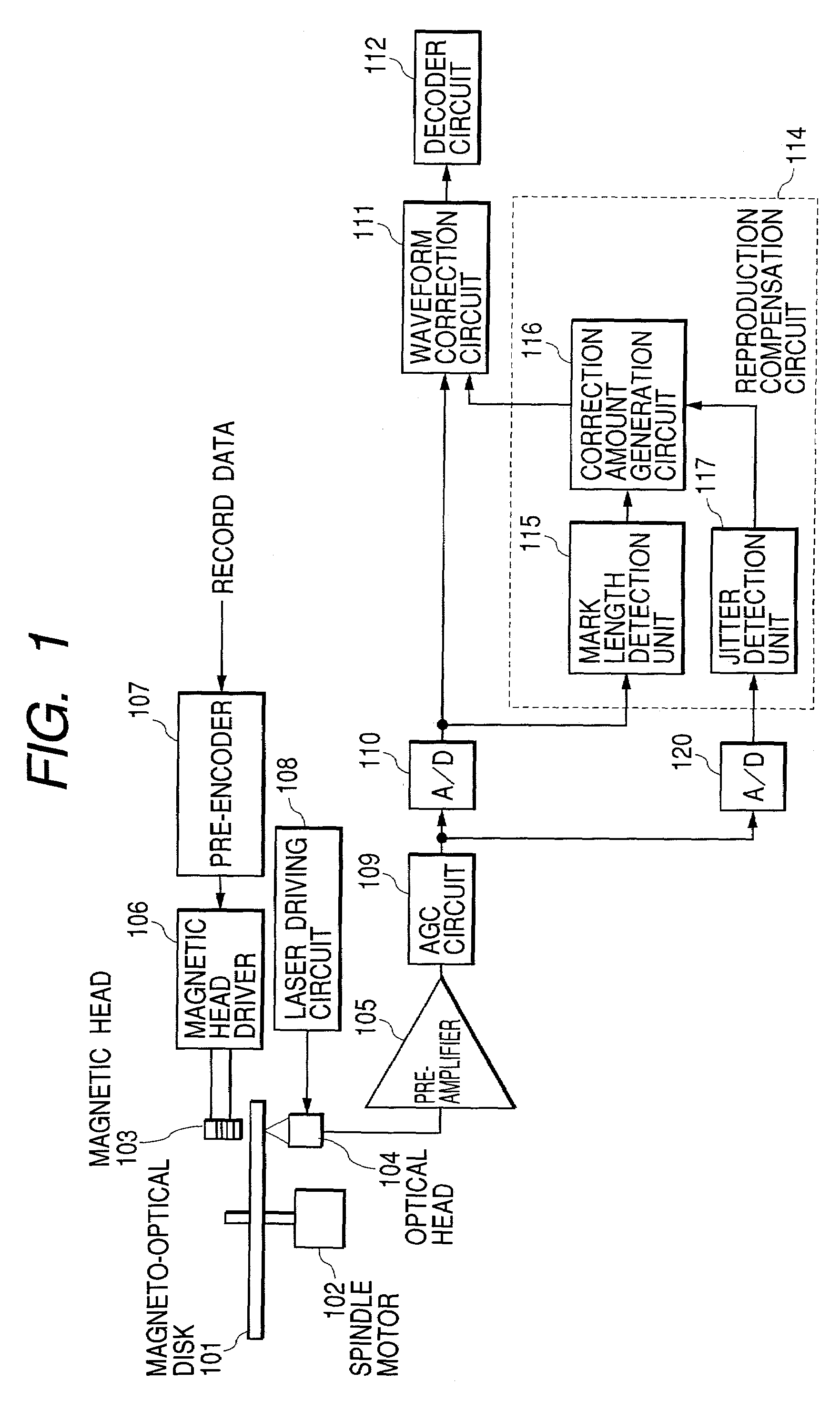
[0057]FIG. 1 is a block diagram showing the configuration of a first embodiment of a magneto-optical reproducing apparatus according to the present invention. In FIG. 1, numeral 101 denotes a magneto-optical disk as an information-recording medium, and numeral 102 denotes a spindle motor for rotating the magneto-optical disk 101 at a predetermined speed. A magnetic head 103 for generating a magnetic field modulated according to a record signal is arranged above the top face of the magneto-optical disk 101, and an optical head 104 is arranged below the bottom face of the disk with opposing the magnetic head 103.

[0058]The optical head 104 radiates a light beam for recording, and records information, or radiates the light beam for reproduction, detects the reflected light from the medium, and reproduces recorded information. At this time, a semiconductor laser (not shown in the drawings) that is a light source for recording and reproduction, and a photosensor (not shown i...

embodiment 2

(Embodiment 2)

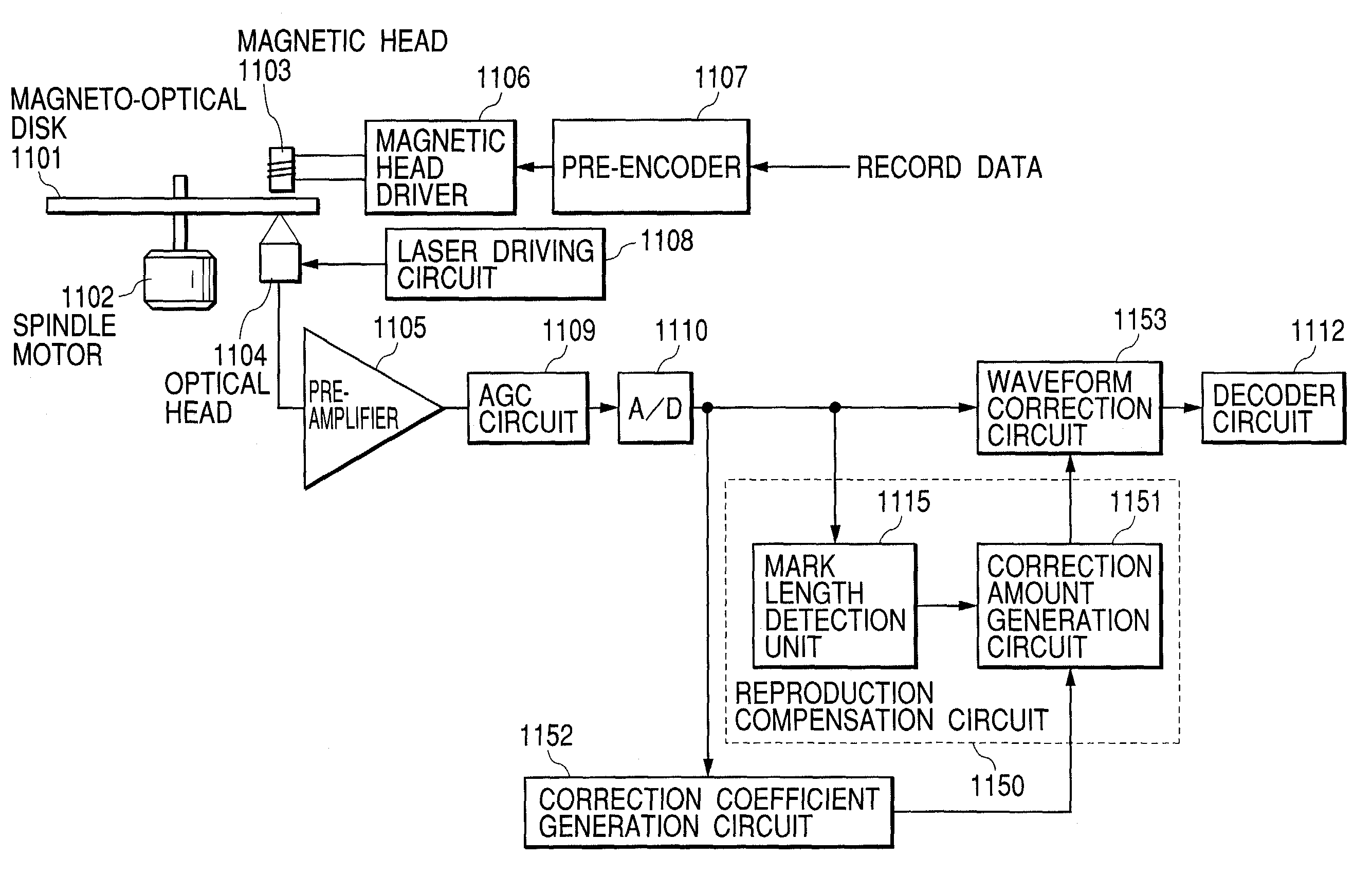
[0113]Next, a second embodiment of the present invention will be explained. The second embodiment is characterized in the generation of a correction coefficient, the generation method of a correction amount, and a correction method in comparison with the above-mentioned embodiment.

[0114]FIG. 10 is a block diagram showing a second embodiment of the present invention. Similar portions as those in FIG. 1 have been assigned the same numerals, consequently, explanations of such portions have been omitted.

[0115]A mark length detection unit 130 in FIG. 10 temporarily determines a reproduced signal that is sampled by PR detection. A jitter detection unit 131 performs PR (1, −1) processing of a sampled RF digital signal 5, and detects a jitter in an edge section. A correction amount generation circuit 132 generates a correction amount of a reproduced signal based on the mark length and jitter. A waveform correction circuit 133 corrects sampled data near an edge of the RF digita...

embodiment 3

(Embodiment 3)

[0135]Next, a third embodiment of the present invention will be explained. This embodiment is different from the second embodiment in a generation method of a correction amount in the correction amount generation circuit 132 in FIG. 10.

[0136]As described above, the size of a stray magnetic field changes with an interval between a magnetic domain wall formed immediately before and a magnetic domain wall which is going to be formed next, i.e., the record mark length to be formed, and the mark length located in front of it. Hence, the edge shift by a waveform deviation is influenced by the record mark length that is going to be formed, and the mark length located ahead of it.

[0137]Then, a correction amount J is generated with the following formula from the kth and (k+1)th mark lengths.

J=−A·n(k)+B·n(k+1)  (8)

Here, n(k) is the kth mark length, and n(k+1) is the (k+1)th mark length.

[0138]Coefficients A and B in Formula (8) are computed by a method of least squares, etc. on t...


PUM

PropertyMeasurementUnit
lengthaaaaaaaaaa
magneticaaaaaaaaaa
optical information reproducing methodaaaaaaaaaa

Abstract

The present invention provides an optical information reproducing method of detecting a record mark formed in an optical information recording medium and generating a reproduced signal, comprising the steps of: detecting a mark length of each record mark on basis of a reproduced signal, and correcting the reproduced signal by a correction amount corresponding to the detected mark length, and an optical information reproducing apparatus for detecting a record mark formed in an optical information recording medium and generating a reproduced signal, comprising: a detection circuit for detecting a mark length of each record mark on basis of a reproduced signal, and a correction circuit for correcting the reproduced signal by a correction amount corresponding to the detected mark length.

Description

BACKGROUND OF THE INVENTION[0001]1. Field of the Invention[0002]The present invention relates to an optical information reproducing method and an optical information reproducing apparatus which are used for optical information recording media such as a magneto-optical disk, a compact disk (CD), and a CD-R, and in particular, is suitable for an optical magnetic reproducing method and an optical magnetic reproducing apparatus which reproduce information by utilizing a photo-electro-magnetic effect.[0003]2. Related Background Art[0004]Up to now in a record / reproduction system by optical information recording media, such as a magneto-optical disk, a compact disk, and a CD-R, it is known that a waveform deviation arises in a recorded signal or a reproduced signal according to the characteristics of a medium. The outline of waveform deviation will be described referring to FIGS. 41A and 41B. FIG. 41A shows a reproduced waveform and FIG. 41B shows decoded data. Here, it is assumed that a r...

Claims


Application Information

Patent Timeline
Patent Type & Authority Patents(United States)
IPC IPC(8): G11B11/10G11B11/18G11B7/005G11B11/105G11B20/10
CPCG11B7/005G11B20/10009G11B11/1053G11B11/10515
Inventor KATAYAMA, TATSUSHI
Owner CANON KK
Why Eureka
Try Eureka