Imaging device and electronic information instrument

a technology of electronic information and imaging device, which is applied in the direction of instruments, semiconductor devices, stereoscopic photography, etc., can solve the problems of inability to obtain accurate three-dimensional images, and inability to accurately fix the positional relationship of l

Active Publication Date: 2014-12-18
SHARP KK
View PDF8 Cites 21 Cited by
  • Summary
  • Abstract
  • Description
  • Claims
  • Application Information

AI Technical Summary

Benefits of technology

[0054]According to the present invention as described above, each image light from a subject which has entered different positions of a lens means is imaged as a plurality of images in a plurality of regions of a solid-state imaging element. Thus, it is possible to render a means for correcting tilts and positional deviations from a three-dimensional image such as a stereo image unnecessary.

Problems solved by technology

In the aforementioned conventional stereo imaging devices, there is an issue of not being able to accurately fix the positional relationship of left and right images due to the two cameras being independent.
If the positional relationship of left and right images cannot be accurately fixed, an accurate three-dimensional image cannot be obtained because the distance to a subject cannot be accurately obtained.

Method used


Image

  • Imaging device and electronic information instrument
  • Imaging device and electronic information instrument
  • Imaging device and electronic information instrument

Examples


embodiment 1

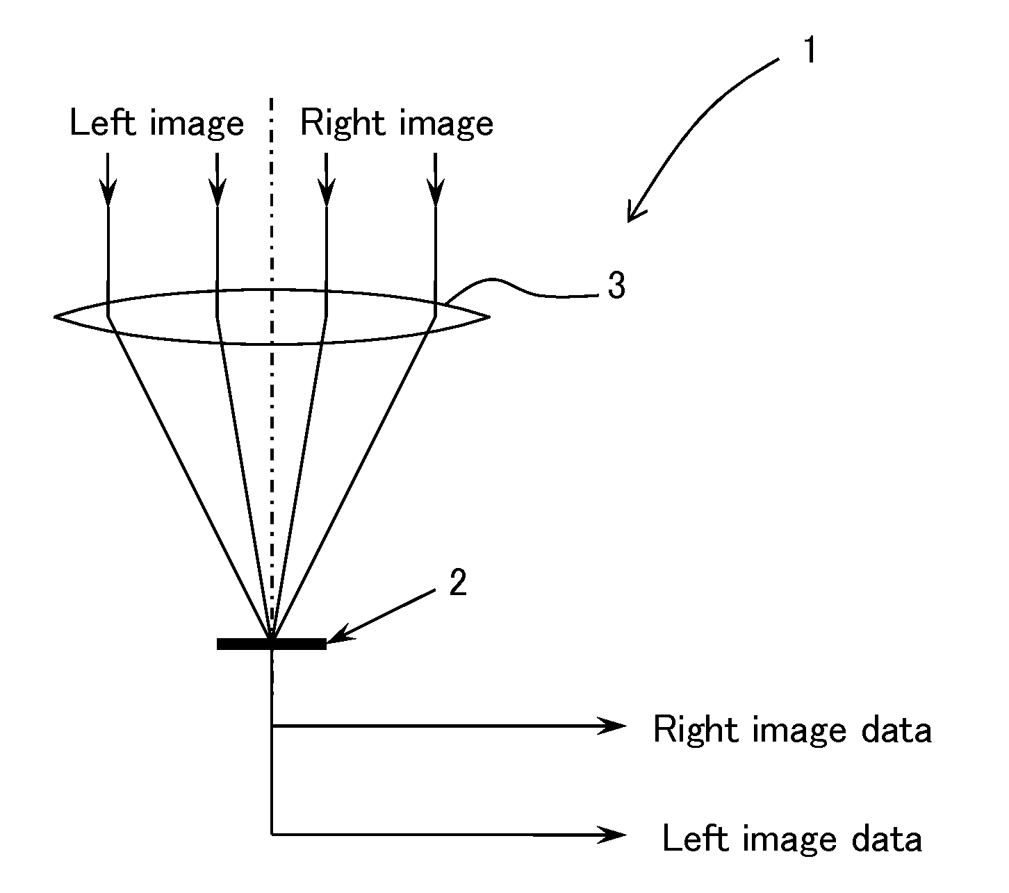
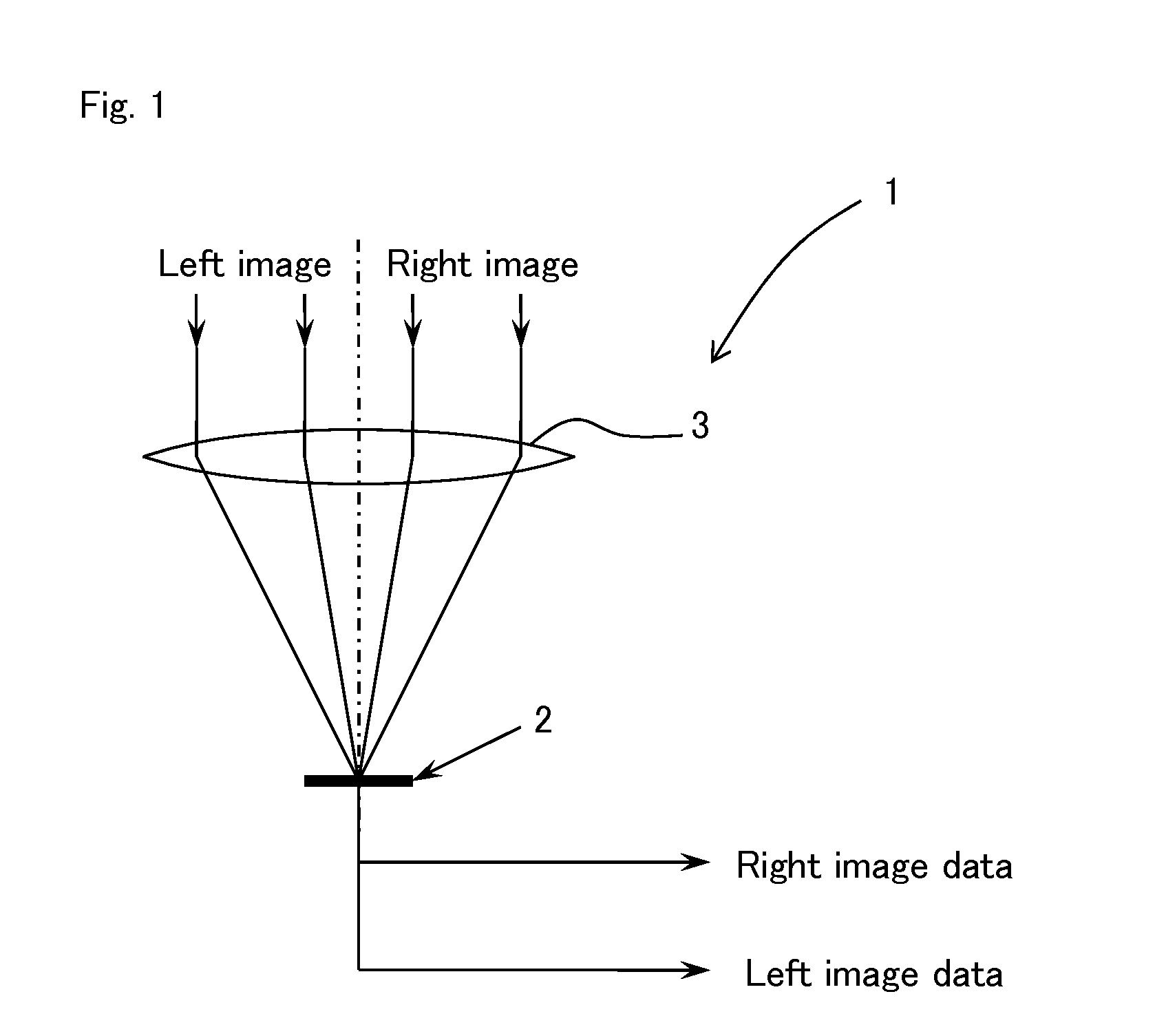
[0096]FIG. 1 is a diagram of a configuration of essential parts of an optical system imaging structure in an imaging device of Embodiment 1 of the present invention.

[0097]In FIG. 1, an imaging device 1 of the present Embodiment 1 has a solid-state imaging element 2 on which a plurality of pixels for photoelectric conversion and imaging of an image light from a subject are arranged in a matrix pattern and a lens means 3 having a single focal point on an imaging surface of the solid-state imaging element 2, and the imaging device 1 is configured to simultaneously or chronologically expose and image each image light as a plurality of images from a subject which has entered different positions of the lens means 3 in a plurality of light receiving regions of each pixel of the solid-state imaging element 2. After a plurality of image data from the solid-state imaging element 2, e.g., two image data on the left and right, are synthesized with a signal synthesizing means for each frame, for...

example 2

[0117]An optical system imaging structure was explained in the above-described Embodiment 1. However, the present Embodiment 2 will explain a case in which an aperture section for separating lights with directivity is provided in a light shielding layer and a plurality of light receiving regions are provided in positions therebelow for each light receiving section (each pixel) as a pixel imaging structure.

[0118]FIG. 4(a) is a cross-sectional view of a solid-state imaging element 2 and a wiring layer as a specific example in an imaging device 11 of Embodiment 2 of the present invention, and FIG. 4(b) is a plan-view of the wiring layer of FIG. 4(a). Although FIG. 4(b) shows six pixels, in actuality, numerous pixels are arranged in a matrix pattern. This can be used in a case of a black and white image without a color filter placed thereon or in a case of a color image with a color filter placed thereon.

[0119]As shown in FIGS. 4(a) and 4(b), in the imaging device 11 of the present Embo...

embodiment 3

[0131]As a pixel imaging structure, the above-described Embodiment 2 explained a case of simultaneously imaging each of image lights from the left and right from a subject, which has entered different positions of a single lens means 3, or two regions of the left and right, in predetermined imaging regions of the solid-state imaging element 2, e.g., left and right light receiving regions for each light receiving section (each pixel). However, in the present Embodiment 3, as a pixel imaging structure, in addition to the content of the above-described Embodiment 1, although a human being views a three-dimensional image with parallax in the left and right directions, a three-dimensional image may be obtained with parallax in up and down directions, or in left and right directions and up and down directions. Furthermore, an excellent three-dimensional image can be obtained by a plurality of directivity including diagonal directions. From such a standpoint, the relationship of the shape ...


PUM


Abstract

A means for correcting tilts and positional deviations from a stereo image is rendered unnecessary. The present invention has a solid-state imaging element 2 on which a plurality of light receiving sections for photoelectrically converting and imaging an image light from a subject are arranged in a matrix pattern and a lens means 3 with a single focal point on an imaging surface of the solid-state imaging element 2. The present invention is configured to simultaneously or chronologically expose and image each imaging light from a subject entering different positions of the lens means 3 as a plurality of images in a plurality of imaging regions for each predetermined imaging regions of the solid-state imaging element 2.

Description

TECHNICAL FIELD[0001]The present invention relates to a stereoscopic imaging device comprising a stereo imaging device that enables imaging of a plurality of images, such as stereoscopic stereo images, and electronic information instrument such as digital still cameras (digital cameras) such as a digital video camera, compact digital camera, mirrorless single-lens camera, and digital single-lens reflex camera, image input camera, scanner, facsimile device, camera-equipped mobile phone device, as well as smartphones, sensors of a self-propelling vacuum cleaner, and human detection sensors of an air conditioning unit using said imaging device in an imaging section as an image input device.BACKGROUND ART[0002]Conventional stereo imaging devices captured images by placing two cameras on the left and right as in human eyes, i.e., left and right images are captured by two cameras on the left and right to obtain left and right image data. The left and right image data is synthesized by eve...

Claims


Application Information

Patent Timeline
Patent Type & Authority Applications(United States)
IPC IPC(8): H04N13/02
CPCH04N13/0207G03B35/08H01L27/14607H01L27/14623H01L27/14625H01L27/14627H04N13/218H01L27/14621H04N25/702H04N13/207H04N13/339
Inventor USHINAGA, TAKEOHATTORI, SHINJI
Owner SHARP KK
Why Eureka
Try Eureka