Position-of-magnetic-pole detecting device and method

a magnetic pole and detection device technology, applied in the direction of electronic commutators, dynamo-electric gear control, dynamo-electric converter control, etc., can solve the problems that the position of a magnetic pole cannot be readily and accurately detected, and the methods of the related arts cannot be applied. to achieve the effect of accurately and quickly detecting the position of a magnetic pol

Active Publication Date: 2006-07-04
FANUC LTD
View PDF12 Cites 22 Cited by
  • Summary
  • Abstract
  • Description
  • Claims
  • Application Information

AI Technical Summary

Benefits of technology

[0010]Accordingly, an object of the present invention is to provide a device and method for detecting the position of a magnetic pole at the time of starting up a motor for the purpose of correcting a deviation of a sensor-mounted position from the position of the magnetic pole. More particularly, the present invention is concerned with a position-of-magnetic-pole detecting device and method for readily and accurately detecting the position of a magnetic pole (position of a rotor).

Problems solved by technology

The foregoing methods of the related arts have a drawback that the position of a magnetic pole cannot be defected readily and accurately.

Method used


Image

  • Position-of-magnetic-pole detecting device and method
  • Position-of-magnetic-pole detecting device and method
  • Position-of-magnetic-pole detecting device and method

Examples


Embodiment Construction

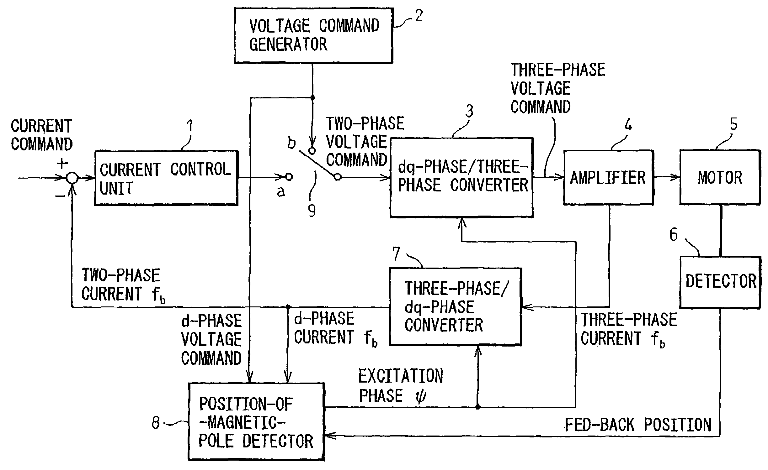
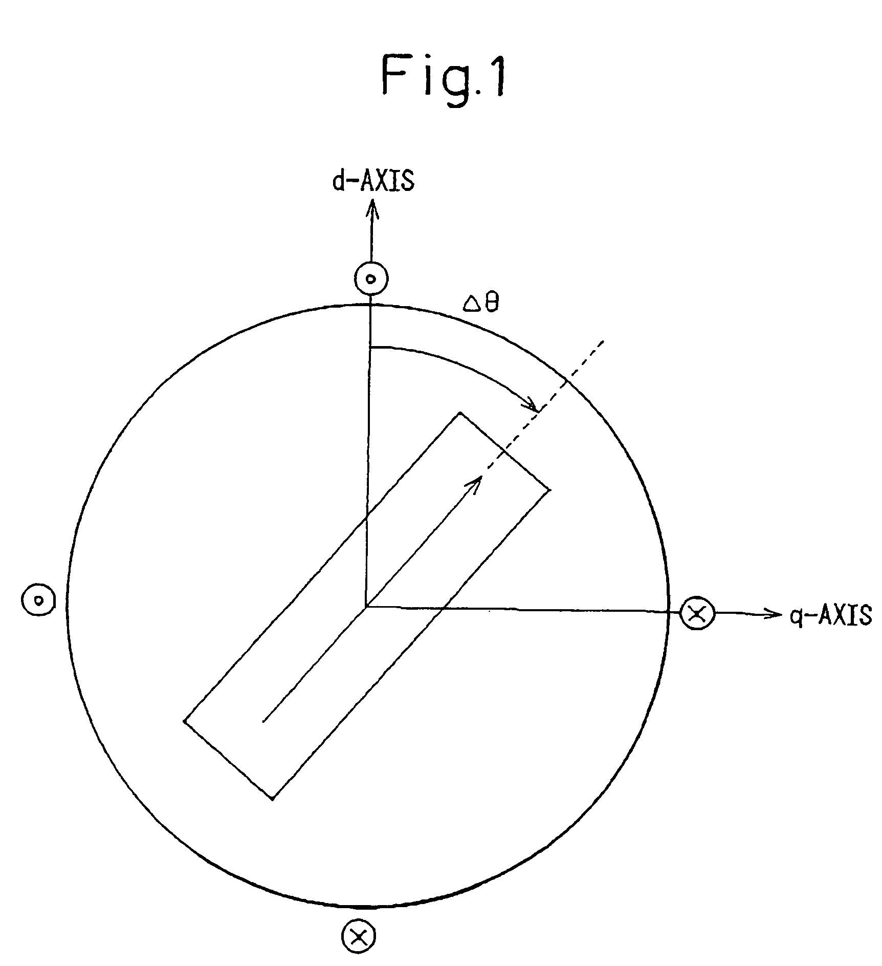
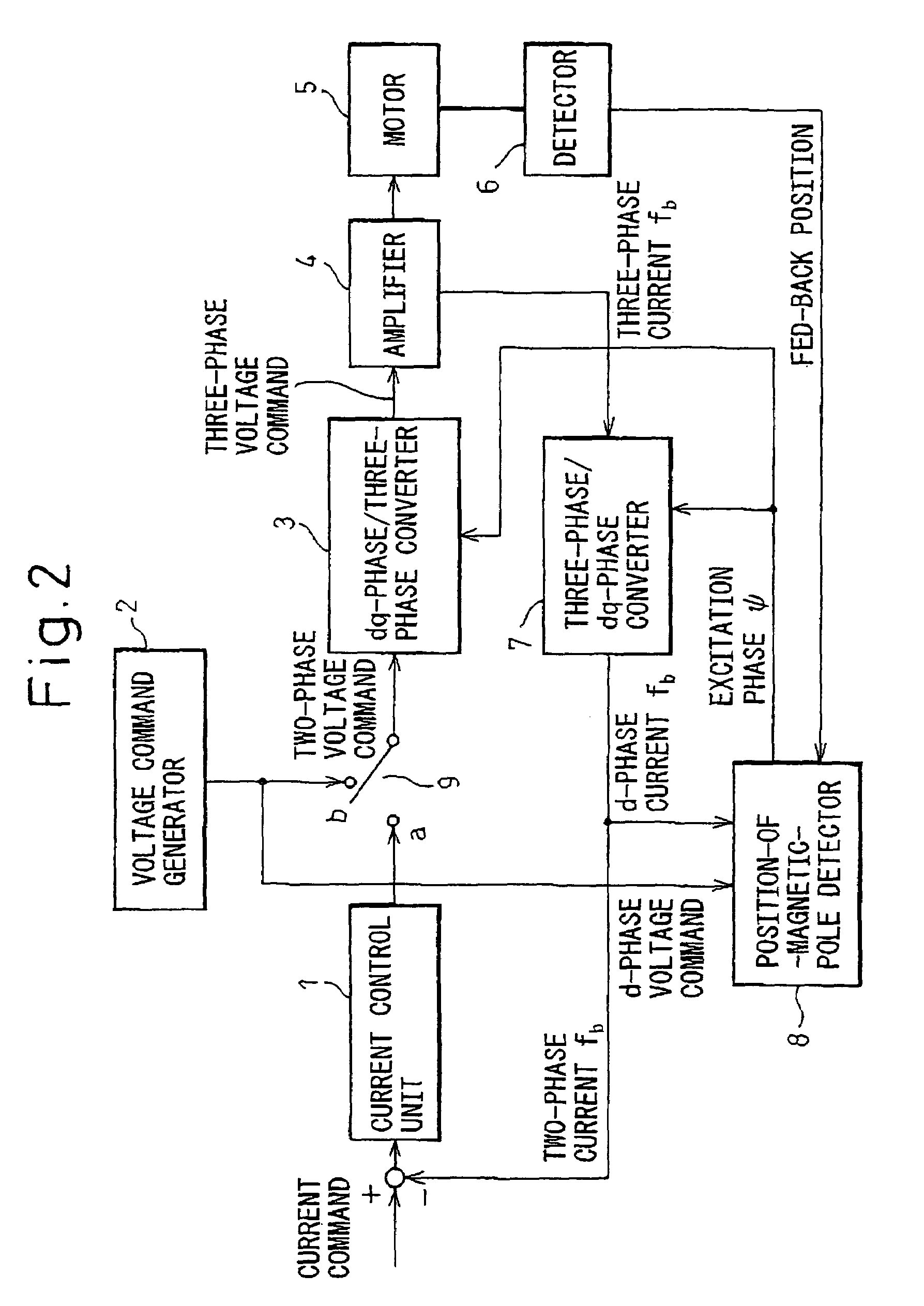
[0022]The structure of a rotor included in a permanent-magnet synchronous motor falls broadly into a surface permanent magnet (SPM) type in which a permanent magnet is bonded to the surface of a rotor, and an interior permanent magnet (IPM) type in which a permanent magnet is embedded in a rotor. In general, the SPM motor is of a non-salient pole type in which a d-axis inductance and a q-axis inductance that are offered by phase windings on an armature are equal to each other, while the IPM motor is of a salient-pole type in which the d-axis and q-axis inductances are different from each other.

[0023]According to the present invention, the property of the salient-pole type IPM motor that the inductances offered by the phase windings are functions of an electrical angle is utilized in order to detect a magnetic pole. The phenomenon that after magnetic saturation occurs, a response in a current varies depending on a direction in which the current flows is utilized in order to check the...


PUM

PropertyMeasurementUnit
electrical angleaaaaaaaaaa
frequencyaaaaaaaaaa

Abstract

A high-frequency voltage whose amplitude is small is applied as a d-phase command voltage, and an excitation phase is changed to a predetermined degree at predetermined intervals, whereby a motor is driven. As the d-phase command voltage has the small amplitude and high frequency, the rotor of the motor does not rotate. A d-phase feed back current is detected, and the product of a derivative of the d-phase feed back current by the high-frequency voltage command is calculated. A high-frequency component is removed from the product. An excitation phase (direction of a magnetic flux) associated with a deviation of 0 or π from the position of a magnetic flux and also associated with a peak value assumed by the product having the high-frequency component removed therefrom is detected. A plurality of thus detected excitation phases is averaged in order to determine the direction of a magnetic flux. The excitation phase associated with one of two peak values assumed by the product is adopted on a fixed basis. Positive and negative rectangular waves having a magnitude causing magnetic saturation are applied as d-phase voltage commands. The polarity of a magnetic pole is determined based on positive and negative d-phase feed back currents. As the direction of a magnetic flux and the polarity thereof are detected separately from each other, the position of a magnetic pole can be detected accurately and reliably.

Description

BACKGROUND OF THE INVENTION[0001]1. Field of the Invention[0002]The present invention relates to detection of the position of a magnetic pole in a rotor included in a synchronous motor, or the like, employing a permanent magnet.[0003]2. Description of the Related Art[0004]In a synchronous motor or a reluctance motor, a desired torque must be generated by causing a current to flow through phase windings according to the position of a magnetic pole in a rotor. The position of a magnetic pole in the rotor is therefore detected using an encoder or another sensor, so that the current will flow in the direction of an appropriate excitation phase. For this purpose, the position of a magnetic pole is detected at the time of starting up a motor in order to obviate the employment of a sensor having absolute values set therein for detection of the position of a magnetic pole or the work of aligning a sensor with a magnetic pole.[0005]Moreover, as methods for detecting the position of a magneti...

Claims


Application Information

Patent Timeline
Patent Type & Authority Patents(United States)
IPC IPC(8): H02P27/04H02P6/18H02P6/06H02P6/08H02P6/17H02P6/182H02P21/00H02P21/34H02P27/08
CPCH02P6/002H02P6/183H02P6/186H02P25/026H02P21/0053H02P21/146H02P21/0025H02P6/28H02P21/18H02P21/32H02P25/03
Inventor TOYOZAWA, YUKIOSONODA, NAOTO
Owner FANUC LTD
Why Eureka
Try Eureka