Method for detecting location of probe bead in capillary bead array

Inactive Publication Date: 2005-11-10
HITACHI SOFTWARE ENG
View PDF3 Cites 3 Cited by
  • Summary
  • Abstract
  • Description
  • Claims
  • Application Information

AI Technical Summary

Benefits of technology

[0008] Thus, it is an object of the present invention to provide a method for accurately identifying the order of probe beads, namely, the types of the probes bound to the probe beads, by readily and accurately detecting the locations of all the beads in a capillary bead array using a fluorescence reading apparatus. It is also an object of the present invention to significantly improve the reliability of the results of biochemical or immunological inspection in which a capillary bead array is used.
[0011] According to the present invention, in a capillary bead array in which a multitude of probe beads are arranged, the locations of all the beads can be detected by the fluorescence reading apparatus, and the order of the probe beads that captured the target biomolecules, namely, the types of the probes that captured the target biomolecules, can be accurately identified simultaneously. Therefore, the accuracy of biochemical or immunological inspection in which a capillary bead array is used can be significantly improved.

Problems solved by technology

However, probe beads that do not capture the fluorescence-labeled target biomolecules are not detected, since no fluorescence is emitted.
Consequently, it is very difficult to accurately know the locations and the number of the probe beads that do not emit fluorescence.
Therefore, it is also impossible to accurately know the types of the probes that have captured the fluorescence-labeled target biomolecules, since it is impossible to accurately know the order of the probe beads that emit fluorescence.

Method used


Image

  • Method for detecting location of probe bead in capillary bead array
  • Method for detecting location of probe bead in capillary bead array
  • Method for detecting location of probe bead in capillary bead array

Examples


embodiments

[0036] In the following, the present invention is described with reference to a comparative example and examples.

example 1

[0039] After the reaction with the sample, the beads are stained by causing a solution of nucleic acid binding dye (SYTO61 (SYTO is a trademark of Molecular Probes Inc.)) to flow into the capillary.

[0040]FIG. 5 shows result images (FIGS. 5A and 5B) and a bead arrangement (FIG. 5C). FIG. 5A shows an image of the situation after the reaction experiment with the sample that includes fluorescence-labeled target DNA has ended. Only three beads near the center have reacted. In contrast, FIG. 5B shows an image after the reaction experiment with the sample has ended, and SYTO 61 is further caused to flow and then washed by cleaning fluid finally takes place. From the result of FIG. 5, it is learned that all the beads are stained with SYTO 61 and emit fluorescence. Thus, it is possible to identify the types of reacted beads by comparing the two images of FIGS. 5A and 5B.

example 2

[0041] After the reaction with the sample that includes fluorescence-labeled target DNA, the beads are stained by causing a highly concentrated fluorescent dye solution to flow into the capillary. FIG. 6 shows result images (FIGS. 6A and 6B) and a bead arrangement (FIG. 6C). FIG. 6A shows an image of the situation after the reaction experiment with the sample that includes fluorescence-labeled target DNA has ended. Only one bead near the center has reacted. By contrast, FIG. 6B shows an image of the situation after the reaction experiment with the sample has ended, and the highly concentrated fluorescent dye solution is caused to flow into the capillary. The beads are shown as an outlined image, since the solution emits intense fluorescence when the highly concentrated fluorescent dye solution is caused to flow. From the result of FIG. 6, it is learned that all the beads can be shown as an outlined image. Thus, it is possible to identify the types of reacted beads by comparing FIGS....


PUM

PropertyMeasurementUnit
Fluorescenceaaaaaaaaaa

Abstract

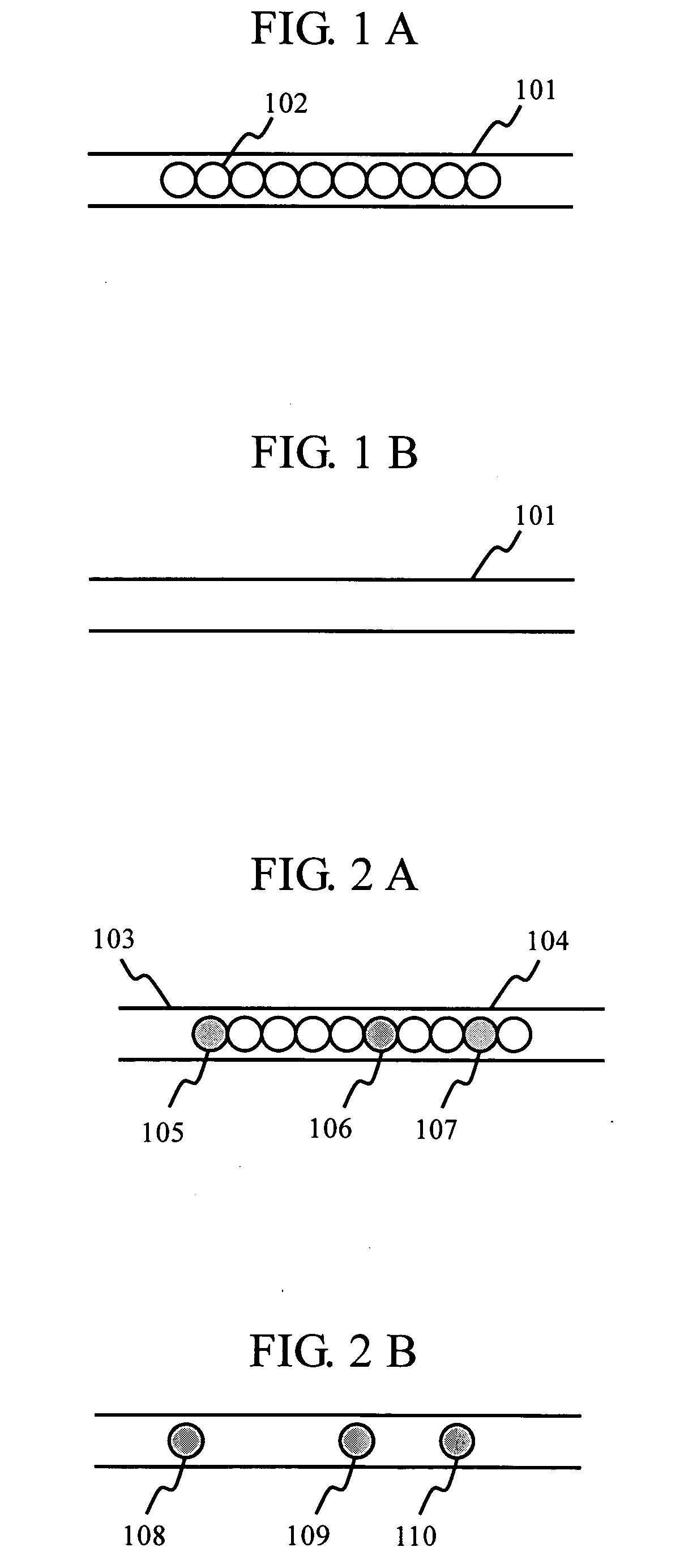
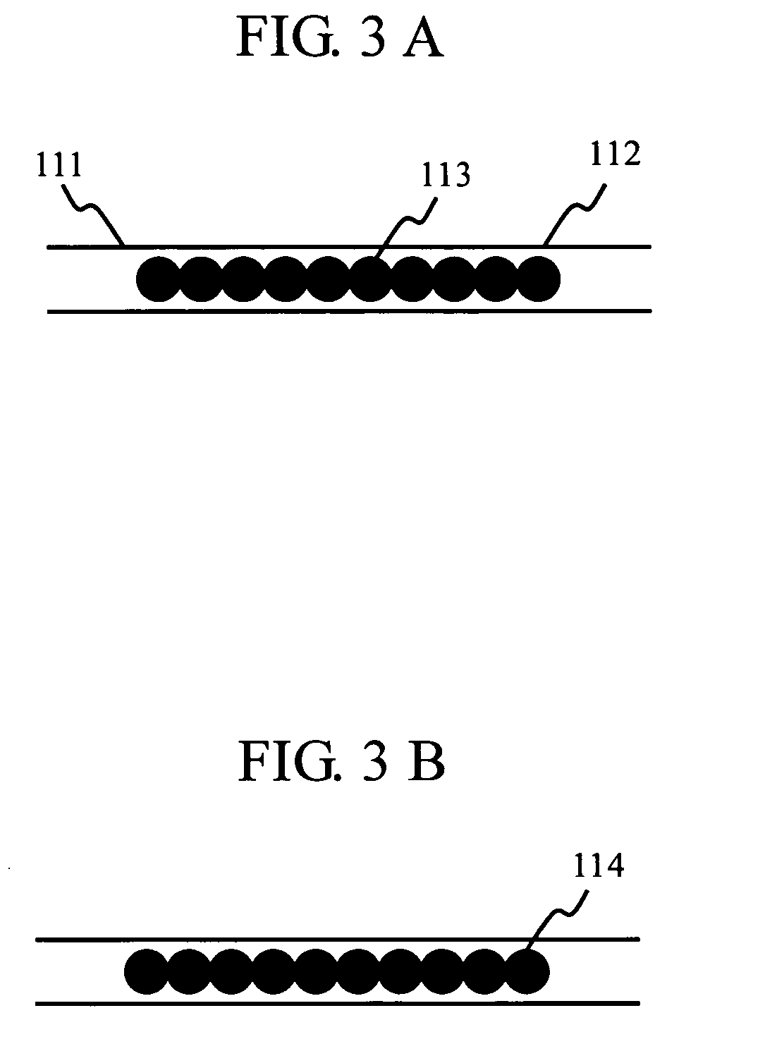
It is an object to provide a method for accurately identifying the order of probe beads, namely, the types of probes bound to the probe beads, by readily and precisely detecting the locations of all the beads in a capillary bead array using a fluorescence reading apparatus. It is also an object to significantly improve the reliability of results of biochemical or immunological inspection in which a capillary bead array is used. Probe beads 102 are arranged in a capillary 101. A solution that includes fluorescence-labeled target biomolecules is introduced into the capillary 101. A fluorescence image that includes the fluorescence spot 108 of a probe bead 105 that captured the biomolecules is obtained by the fluorescence reading apparatus. A solution that includes fluorescent material for staining all the beads is introduced into the capillary 101. A fluorescence image that includes the fluorescence spot area 114 of all the probe beads 113 is obtained by the fluorescence reading apparatus. The location and the order of the probe bead 105 that has captured the biomolecules is accurately determined by overlaying the fluorescence image that includes the fluorescence spot 108 of the probe bead that has captured the biomolecules and the fluorescence image that includes the fluorescence spot area 114 of all the probe beads 113.

Description

BACKGROUND OF THE INVENTION [0001] 1. Field of the Invention [0002] The present invention relates to a method for detecting the locations of particulate beads, and especially to a method for detecting the locations of beads in a capillary bead array in which the beads are arranged in a capillary formed on soft resin, for example. [0003] 2. Background Art [0004] Concerning a capillary bead array in which probe beads bound to probes for detecting biomolecules are arranged in a capillary formed on soft resin, for example, the following JP Patent Publication (Kokai) No. 2000-346842 A is cited as prior art relating to the confirmation of bead locations. JP Patent Publication (Kokai) No. 2000-346842 A discloses a method by which marker beads whose color or size is different from those of probe beads are disposed at intervals of a predetermined number of the probe beads, as a method for confirming the locations of the probe beads arranged inside a capillary. In this case, the marker beads ...

Claims


Application Information

Patent Timeline
IPC IPC(8): C12Q1/68G01N21/05G01N21/75G01N21/78G01N21/64G01N33/48G01N33/50G01N33/53G01N33/543G01N33/551G01N33/58
CPCG01N21/6428G01N21/6456G01N33/54313G01N2021/751G01N2021/052G01N2021/6439G01N33/582
Inventor KOGI, OSAMU
Owner HITACHI SOFTWARE ENG
Why Eureka
Try Eureka