Laser Processing Apparatus, Laser Processing Method, and Method For Making Settings For Laser Processing Apparatus

a laser processing and laser processing technology, applied in the direction of optical elements, manufacturing tools, instruments, etc., can solve the problems of changing the focal distance, the amount of heat retained in the laser oscillator, and users performing extremely complicated adjustment operations, so as to eliminate operations and cope with thermal lens effects extremely easily

Inactive Publication Date: 2009-06-18
KEYENCE
View PDF18 Cites 19 Cited by
  • Summary
  • Abstract
  • Description
  • Claims
  • Application Information

AI Technical Summary

Benefits of technology

[0034]This enables corrections according to the deviation of the focus position caused by thermal lens effects which are expected to occur during actual processing, at the time of setting the laser processing condition. As a result, it is possible to eliminate operations for manually adjusting the height of the installed laser processing apparatus and the like for adjusting the working distance, thereby offering the advantage of coping with thermal lens effects extremely easily.

Problems solved by technology

On the other hand, laser crystals induce the phenomenon of deformations of the end surfaces of the crystals, which is called thermal lens effects due to heat, which induces the problem of changes of the focal distance.
Unfortunately, the amount of heat retained within the laser oscillator which affects the thermal lens effects depends on the values set for the laser oscillator.
Accordingly, every time the laser processing conditions are changed, there is a need for resetting the working distance, which has forced users to perform extremely complicated adjustment operations.
This may induce different degrees of thermal lens effects in the respective processing blocks, thereby resulting in the problem of difficulty in performing processing on block-by-block basis with the same processing quality.

Method used


Image

  • Laser Processing Apparatus, Laser Processing Method, and Method For Making Settings For Laser Processing Apparatus
  • Laser Processing Apparatus, Laser Processing Method, and Method For Making Settings For Laser Processing Apparatus
  • Laser Processing Apparatus, Laser Processing Method, and Method For Making Settings For Laser Processing Apparatus

Examples


Embodiment Construction

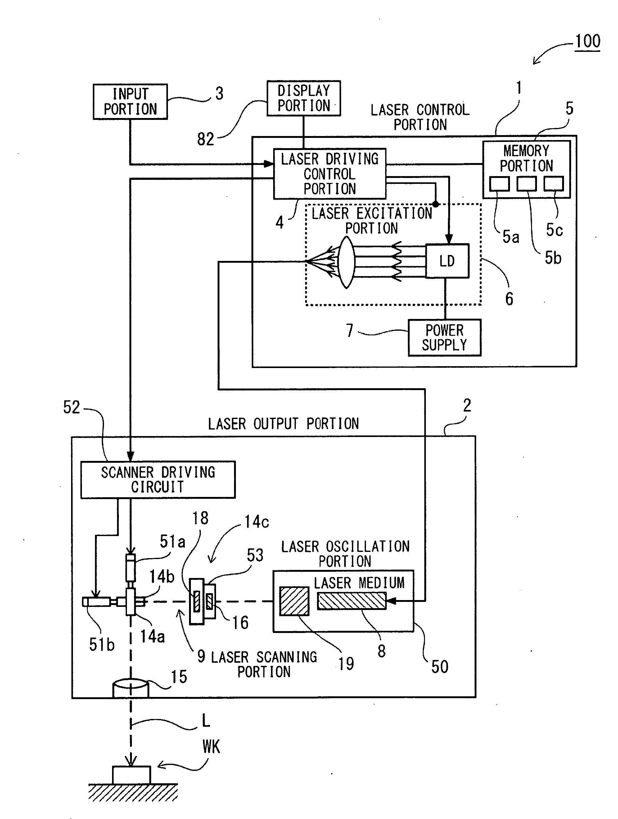
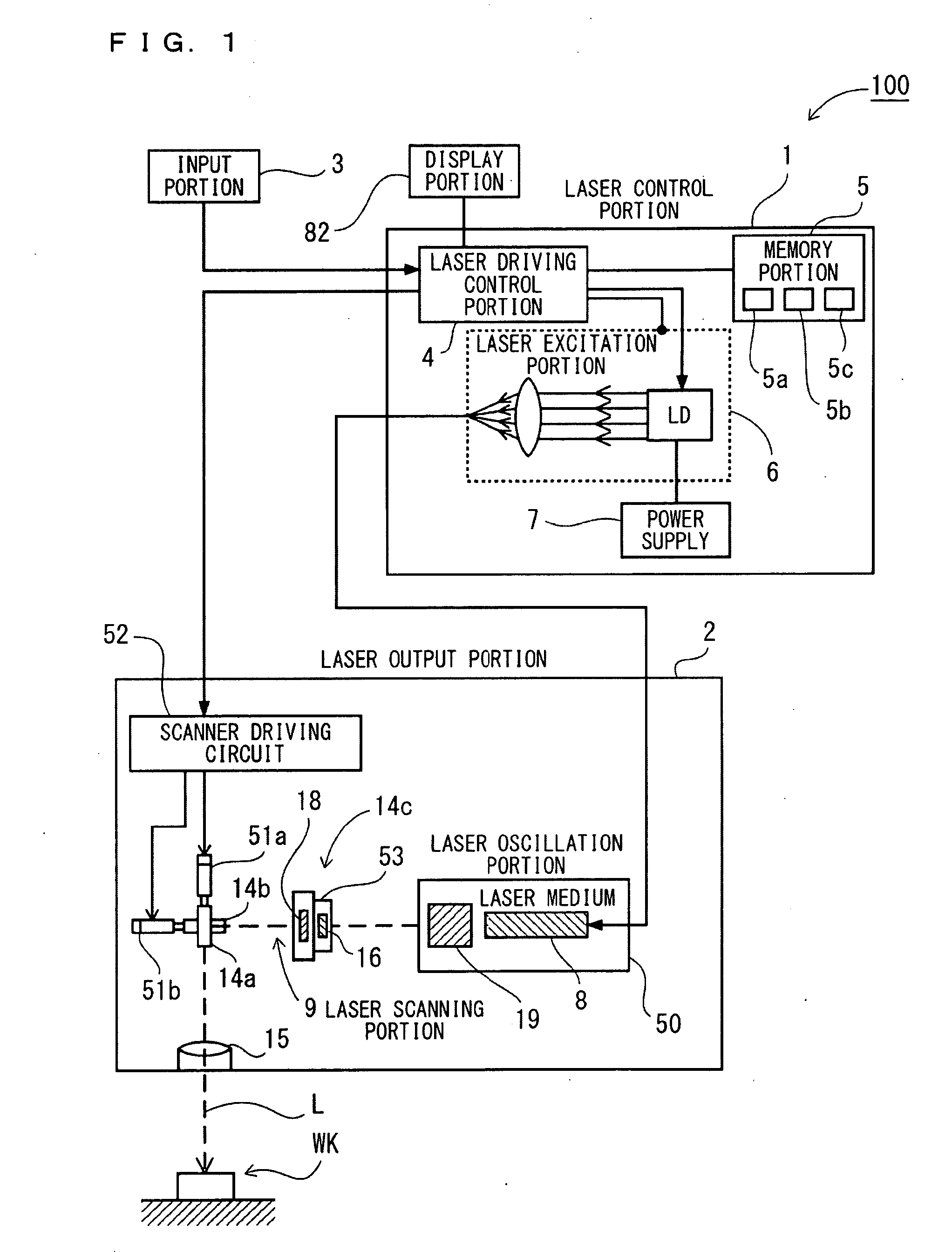
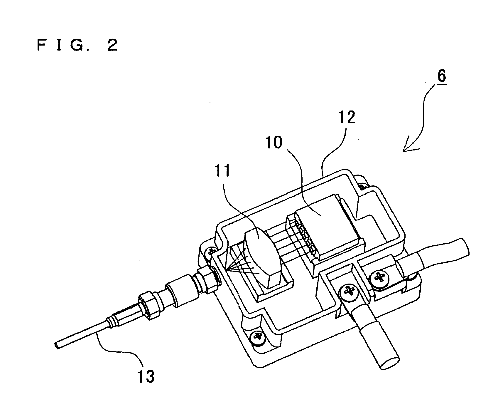
[0058]Hereinafter, an embodiment of the present invention will be described, with reference to the drawings. However, in the embodiment which will be described later, there will be exemplified a laser processing apparatus, a laser processing method and a method for making settings for a laser processing apparatus for concretizing the technical concepts of the present invention and, in the present invention, the laser processing apparatus, the laser processing method and the method for making settings for the laser processing apparatus are not limited to those which will be described later. Further, in the present specification, the members defined in the claims are never limited to the members in the embodiment. Particularly, the dimensions, the materials, the shapes and the relative placements of components which will be described in the embodiment are merely illustrative and are not intended to limit the scope of the present invention, unless otherwise specified. Further, the size...


PUM

PropertyMeasurementUnit
center wavelengthaaaaaaaaaa
quantum efficiencyaaaaaaaaaa
diameteraaaaaaaaaa

Abstract

It is an object to enable easily adjusting a focus position for coping with thermal lens effects. There is provided a laser-light scanning portion including a Z-axis scanner capable of adjusting the focus position of laser light in the direction of the optical axis, an X-axis scanner and a Y-axis scanner. Further, there are provided a laser driving control portion for controlling a laser oscillation portion and the laser-light scanning portion, a processing-condition setting portion for setting a laser-light outputting condition and a processing pattern as processing conditions for processing in a desired processing pattern, and an amount-of-correction identification section for identifying, as an amount of focus-position correction, the deviation of the focus position in the direction of the optical axis which is caused by thermal lens effects induced based on the laser-light outputting condition set by the processing-condition setting portion. During irradiation of the laser light, the laser driving control portion scans the laser light, in such a way as to add the amount of focus-position correction identified by the amount-of-correction identification section to the processing condition set by the processing-condition setting portion.

Description

CROSS-REFERENCE TO RELATED APPLICATIONS[0001]The present application claims foreign priority based on Japanese Patent Application No. 2007-323686, filed Dec. 14, 2007, the contents of which is incorporated herein by reference.BACKGROUND OF THE INVENTION[0002]1. Field of the Invention[0003]The present invention relates to a laser processing apparatus for directing laser light to a to-be-processed target for performing processing such as printing, such as a laser marking apparatus, a laser processing method and a method for making settings for a laser processing apparatus.[0004]2. Background Art[0005]Laser processing apparatuses are adapted to scan laser light over a predetermined area for directing the laser light to the surface of a to-be-processed target (work) such as a component and product for performing processing such as printing and marking thereon. FIG. 22 illustrates an exemplary structure of a laser processing apparatus. The laser processing apparatus illustrated in the fi...

Claims


Application Information

Patent Timeline
Patent Type & Authority Applications(United States)
IPC IPC(8): H01S3/101H01S3/11B23K26/00B23K26/046B23K26/082
CPCB23K26/0807G02B26/12B41J2/471B23K26/082
Inventor SATO, MASAOYAMAKAWA, HIDEKI
Owner KEYENCE
Why Eureka
Try Eureka