Optical disc apparatus and optical disc replay method

a technology of optical discs and optical discs, applied in the field of optical disc apparatuses and optical disc replay methods, can solve the problems of complex objective lens control mechanisms, consequently making themselves sophisticated and large, and achieve the effect of accurately reproducing information from an optical disc and simple configuration

Inactive Publication Date: 2009-10-22
SONY CORP
View PDF10 Cites 8 Cited by
  • Summary
  • Abstract
  • Description
  • Claims
  • Application Information

AI Technical Summary

Benefits of technology

[0016]According to the present invention, when a reproducing light beam of substantially collimated light is emitted so as to include a target position, it is possible to detect that the reproducing light beam is blocked by a recording mark according to the outcome of detection in a detection region at the confocal point of the target position and recognize the presence or absence of a recording mark at the target position so that it is now possible to realize an optical pickup and an optical disc apparatus having a simple configuration that can accurately reproduce information from an optical disc.

Problems solved by technology

Thus, there arises a problem that it inevitably needs a complex objective lens control mechanism to consequently make itself sophisticated and large.

Method used


Image

  • Optical disc apparatus and optical disc replay method
  • Optical disc apparatus and optical disc replay method
  • Optical disc apparatus and optical disc replay method

Examples


first embodiment

(1) First Embodiment

(1-1) Configuration of Optical Disc

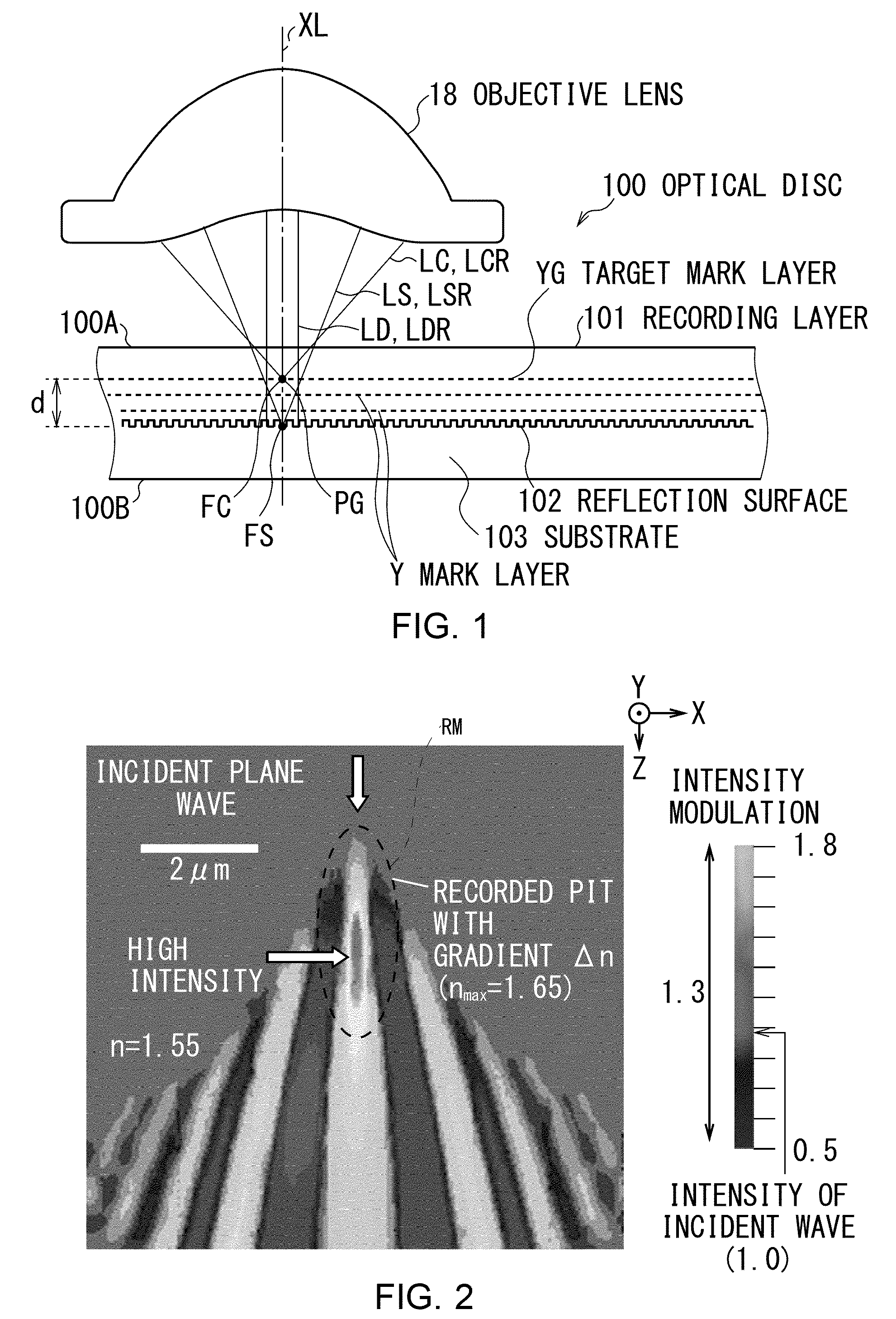
[0033]FIG. 1 schematically shows a cross section of an optical disc. Referring to FIG. 1, the optical disc 100 is adapted to record information as a recording mark RM that represents a piece of information is formed in a recording layer 101. The optical disc is also adapted to reproduce information according to the presence or absence of a recording mark RM.

[0034]The recording layer 101 is typically formed by mixing a resin material with a predetermined photo-polymerization initiator and hardened. As a recording light beam LC is converged to the recording layer 101, the temperature of the recording layer rises violently at and around the focus FC to gasify the photo-polarization initiator and form a bubble at and around the focus.

[0035]The produced cavity operates as a recording mark RM. The recording mark RM shows a refractive index that remarkably changes at the boundary surface of the resin material relative to the cavity so ...

second embodiment

(2) Second Embodiment

[0136](2-1) Configuration of Optical Disc Apparatus and that of Optical Disc

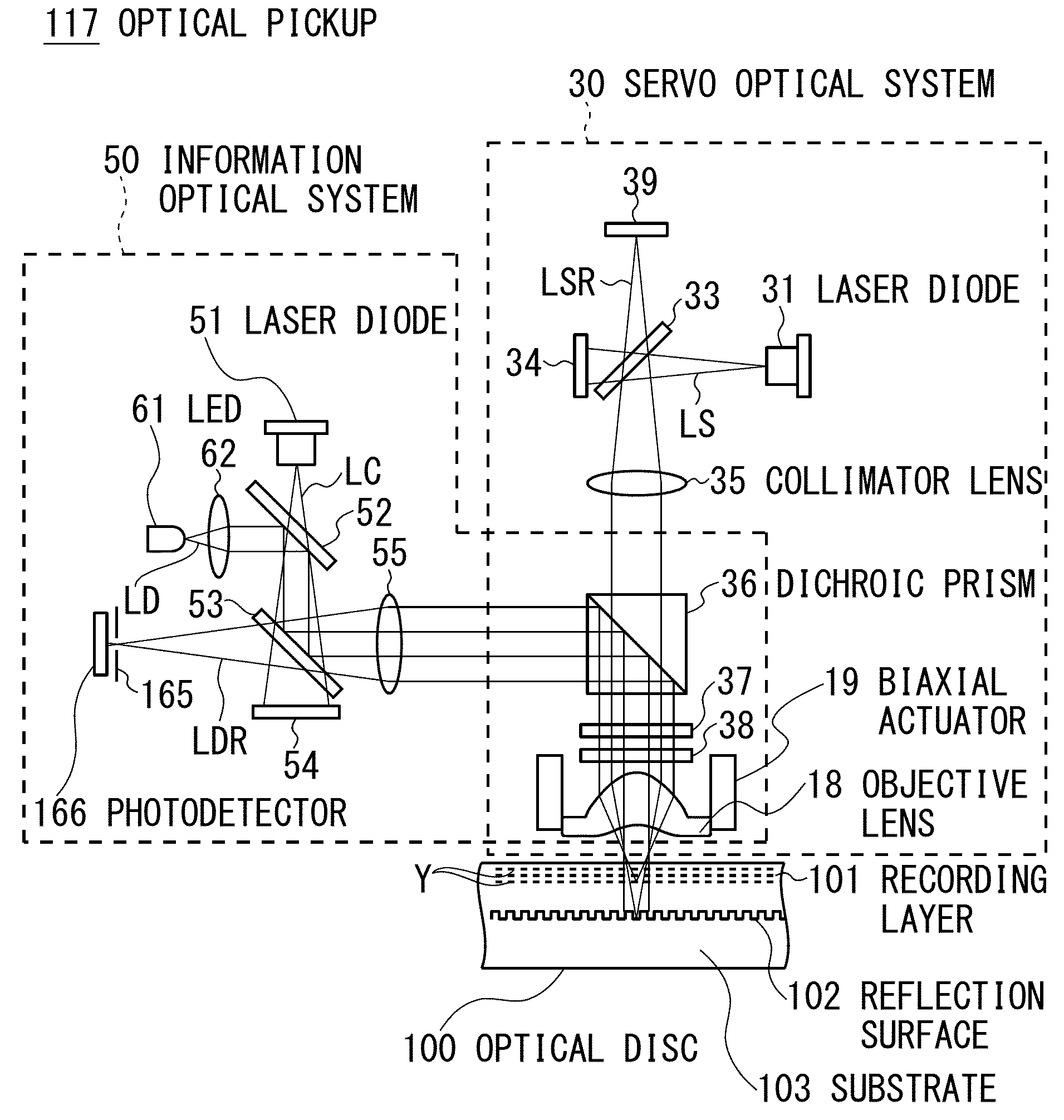
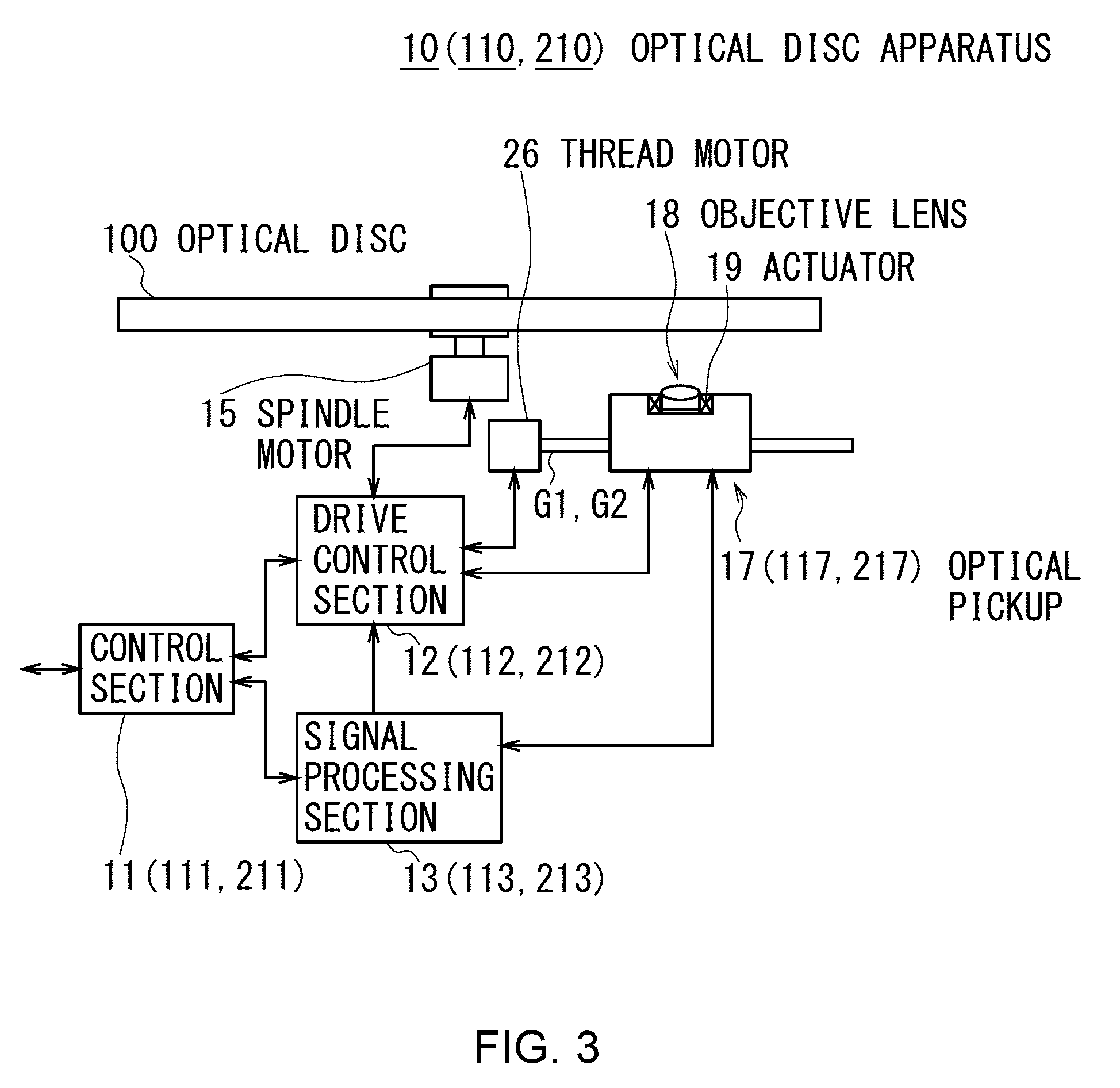
[0137]When compared with the optical disc apparatus 10 of the first embodiment, the optical disc apparatus 110 (FIG. 3) of the second embodiment differs in terms of a control section 111, a drive control section 112, a signal processing section 113 and an optical pickup 117 thereof that correspond respectively to the control section 11, the drive control section 12, the signal processing section 13, and the optical pickup 17 of the first embodiment.

[0138]Like the control section 11, the control section 111 comprehensively controls the optical disc apparatus 110. The signal processing section 113 generates a focus error signal similar to its counterpart of the first embodiment but it generates a tracking error signal by means of a technique different from the first embodiment.

[0139]Like the drive control section 12, the drive control section 112 controls the objective lens 18 for focus co...

third embodiment

(3) Third Embodiment

[0176](3-1) Configuration of Optical Disc Apparatus and that of Optical Disc

[0177]When compared with the optical disc apparatus 10 of the first embodiment, the optical disc apparatus 210 (FIG. 3) of the third embodiment differs in terms of a control section 211, a drive control section 212, a signal processing section 213 and an optical pickup 217 thereof that correspond respectively to the control section 11, the drive control section 12, the signal processing section 13 and the optical pickup 17 of the first embodiment.

[0178]Like the control section 11, the control section 211 comprehensively controls the optical disc apparatus 210. The signal processing section 213 generates a focus error signal and a tracking error signal by means of a technique different from the first embodiment.

[0179]Like the drive control section 12, the drive control section 212 controls the objective lens 18 for focus control and tracking control according to the focus error signal and ...


PUM

PropertyMeasurementUnit
diameteraaaaaaaaaa
wavelengthaaaaaaaaaa

Abstract

When an optical disc apparatus reproduces information from an optical disc, it converges a reading light beam emitted from an LED to substantially collimated light and projects it to the optical disc to cause it to be reflected by reflection surface thereof so as to make it become a reading reflected light beam. Then, the apparatus converges the reading reflected light beam by a mark layer selection lens, detects the reading reflected light beam passing through the target position by a detection region located at the confocal point of the target position and generates a detection signal. Subsequently, the apparatus recognizes the presence or absence of a recording mark based on the detection signal to reproduce the information. Thus, the apparatus can detect the state of the reading reflected light beam observed when it passes the target position and can recognize the presence or absence of a recording mark.

Description

CROSS REFERENCE TO RELATED APPLICATIONS[0001]The present invention contains subject matter related to Japanese Patent Application JP 2008-108228 filed in the Japanese Patent Office on Apr. 17, 2008, the entire contents of which being incorporated herein by reference.BACKGROUND OF THE INVENTION[0002]1. Field of the Invention[0003]The present invention relates to an optical disc apparatus and an optical disc replay method that can suitably be used, for instance, for an optical disc apparatus for reproducing information from an optical disc where information is recorded.[0004]2. Description of the Related Art[0005]Optical disc apparatus for emitting a light beam onto an optical disc such as a compact disc (CD), a digital versatile disc (DVD) or a Blu-ray disc (registered trademark: to be referred to as BD hereinafter) and reproducing information from the disc by reading reflected light have become very popular.[0006]With regard to optical discs, it is known that the size of the light s...

Claims


Application Information

Patent Timeline
Patent Type & Authority Applications(United States)
IPC IPC(8): G11B7/00
CPCG11B7/00451G11B7/00452G11B7/005G11B7/0908G11B2007/0013G11B7/131G11B7/133G11B7/1381G11B7/0938
Inventor SAITO, KIMIHIROHAYASHI, KUNIHIKO
Owner SONY CORP
Why Eureka
Try Eureka