Method of fabricating multi-channel devices and multi-channel devices therefrom

a multi-channel device and fabrication method technology, applied in the direction of manufacturing tools, laminated elements, light and heating equipment, etc., can solve the problems of difficult fabrication of smaller and more compact multi-channel devices to meet economic constraints, significant increase in the cost of wire edm, compared to other techniques, and long fabrication time, etc., to achieve improved fabrication methods, lower pressure, and lower equipment cost

Inactive Publication Date: 2005-02-08
BATTELLE MEMORIAL INST
View PDF32 Cites 55 Cited by
  • Summary
  • Abstract
  • Description
  • Claims
  • Application Information

AI Technical Summary

Benefits of technology

to provide lower-cost multi-channel devices using improved fabrication methods. More particularly, in a preferred embodiment, the invention relates to a continuous, or semi-continuous, fabrication process wherein two ribbons of sheet material edge webs and, optionally, additional webs and/or support members are welded or otherwise attached to a ribbon of sheet material base web. The resulting partial laminate is then separated into subassemblies, each subassembly comprising a base and two edge strips and, optionally, additional strips which cooperate to define a plurality of open channels with, optionally, support members. The subassemblies, depending upon the desired application, may be configured in an almost infinite variety of designs. Subsequen

Problems solved by technology

Fabricating smaller and more compact multi-channel devices to meet economic constraints can be particularly difficult, especially when numerous small channels are required and the channels are in close proximity to one another.
While useful for forming relatively deep, narrow channels in solid material and minimizing assembly and alignment issues, wire EDM, compared to other techniques, is significantly more expensive.
In addition, some practical limitations exist on channel lengths and fabrication time can be lengthy.
The bonding process itself

Method used


Image

  • Method of fabricating multi-channel devices and multi-channel devices therefrom
  • Method of fabricating multi-channel devices and multi-channel devices therefrom
  • Method of fabricating multi-channel devices and multi-channel devices therefrom

Examples


Embodiment Construction

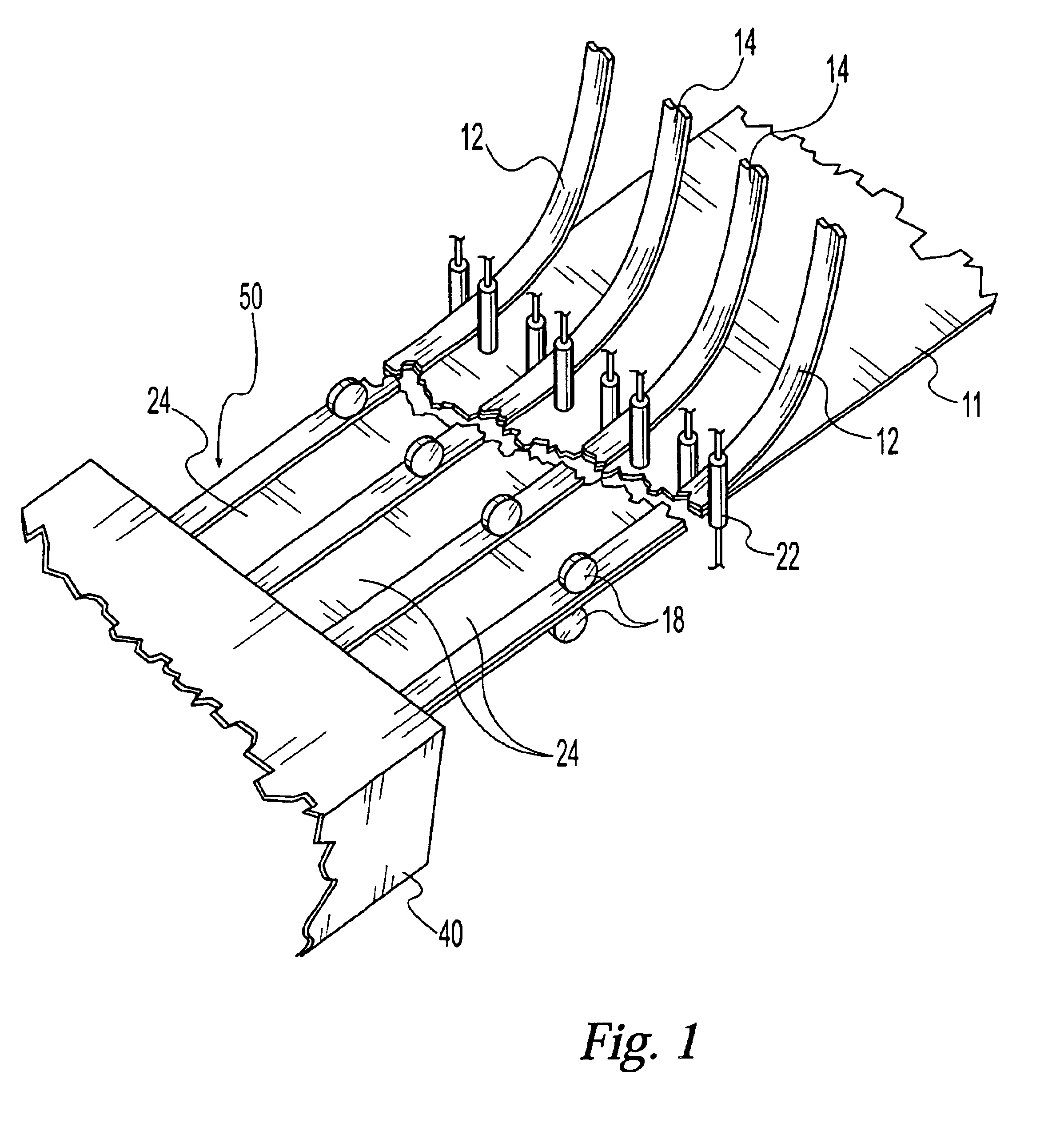
FIG. 1 shows a first step in fabricating the typical subassembly 10, 20, 60 (FIGS. 3, 4, and 5, respectively) for eventual inclusion in a completed stack 100 (FIG. 8). Beginning with a feed of the desired metals, plastics, ceramics, or other suitable materials of construction, the main components of the typical subassembly 10 (FIG. 3), the base web 11 and at least two edge webs 12, are fed together while being guided and aligned. As it is desirable to adapt the present invention to a continuous high-speed process, coil-fed operations, well-known to those of ordinary skill in the art, may be employed with certain materials such as metals and plastics. Alternatively, any desired length of metal or other material may be fed by other well-known methods. While a standard alignment method using alignment rollers 22 is shown, it will be appreciated by one skilled in the art, that other alignment methods could be utilized with equal success. Alignment plates, for example, could be employed ...


PUM

PropertyMeasurementUnit
Timeaaaaaaaaaa
Adhesivityaaaaaaaaaa

Abstract

A multi-channel device fabrication process and multi-channel devices made therefrom wherein two ribbons of sheet material edge webs and, optionally, additional webs and/or support members are secured to a ribbon of sheet material base web. The resulting partial laminate is separated into subassemblies, each subassembly comprising a base and two edge strips and, optionally, additional strips which cooperate to define a plurality of open channels with, optionally, support members. A plurality of subassemblies may stacked together with an end plate to form a complete stack, the edges of each subassembly being attached together to form a complete unit. One or more headers or manifolds may be attached to the outside of the complete unit to provide combined fluid inlet to, and egress from, the unit.

Description

FIELD OF THE INVENTIONThe present invention relates to a method of fabricating multi-channel devices and multi-channel devices made therefrom. In particular, multi-channel devices in which channel groups are arranged in a cross-flow design. Such devices may include, for example, chemical reactors, heat exchangers, and combinations thereof. Additional applications include other chemical unit operations such as vaporization, condensation, and distillation. In each case, fluids or fluid-like streams, e.g., gases, liquids, fluidized solids, suspended solids, or combinations thereof, flow through the channels.BACKGROUND OF THE INVENTIONMulti-channel devices have particular use in the field of chemical unit operations. For example, a plurality of channels can enable improved pressure containment and flow distribution when compared with a single channel capable of handling the same flow and can also provide greater surface area per unit volume. Examples of the most basic multi-channel devi...

Claims


Application Information

Patent Timeline
IPC IPC(8): B21D53/04B23K31/02B21D53/02B23P15/26F28D9/00B23K26/08
CPCB21D53/04B23K26/0846B23K31/02F28D9/0062B23P15/26Y10T29/49359Y10T29/49393Y10T29/49904
Inventor SCHMITT, STEPHEN C.
Owner BATTELLE MEMORIAL INST
Why Eureka
Try Eureka