Trigger lock

a trigger lock and lock technology, applied in the field of trigger locks, can solve the problems of not understanding how to correctly and safely operate or handle the weapon, not being able to properly place the weapon, and being careless with the weapon, etc., and achieve the effect of convenient placemen

Inactive Publication Date: 2005-02-08
DOIRON GERALD J
View PDF7 Cites 15 Cited by
  • Summary
  • Abstract
  • Description
  • Claims
  • Application Information

AI Technical Summary

Benefits of technology

Another object of the invention is to provide a device that is relatively easy to place in the no-fire position and requires a positive action to put the weapon in the fire position.

Problems solved by technology

There can be a danger if someone unauthorized to operate the weapon gains access to the weapon and is able to “fire” the weapon especially if the weapon is loaded.
This unauthorized operator may not realize that the weapon is loaded or may not understand how to correctly and safely operate or handle the weapon.
They may just be careless with the weapon and not realize at is loaded.
The problems with some types of devices are that they can be defeated or manipulated rather easily so that the weapon can be put in the fire position without much effort or intellect.
While these devices may be appropriate for careful responsible adult users, these devices are not the best for curious children.
Children often times are intrigued by weapons and may not fully understand the danger of handling a weapon especially if the weapon is left loaded.
While separate devices that lock the trigger can be effective, there are problems in that the devices detach from the weapon and can be misplaced or dropped in the snow or mud.
It these devices come in two or more pieces that can become detached from one another, this contributes to the possibility of loss.
This can be a dis-incentve to replacing the device on the weapon once removed, thus endangering unauthorized persons when the device is not replaced.
Other clip or attachment type devices suffer from similar disadvantages.
Another disadvantage of the attachable type devices is that many only attach to one side of the weapon and must be oriented to the weapon to be attached property.
This can make them difficult to reattach to the weapon in low light, the dark or with gloves or mittens.
Another disadvantage to these types of devices is that they must be stored somewhere when removed while the weapon is in the fire position.
The storage spot will many times be the users pocket which can be bulky and uncomfortable.
In bush conditions the device could possibly fall out and become lost.
The user could also put the device down once removed, and this raises the possibility of forgetting it if they were to leave in a hurry.
There are weight issues too that can arise for one who is hiking or hunting and needs to carry gear that is of minimal weight.
Another disadvantage of other devices is that they can make holstering the weapon in a standard holster difficult.
This is due to the shape and size of some of the art.

Method used


Image

  • Trigger lock
  • Trigger lock
  • Trigger lock

Examples


second embodiment

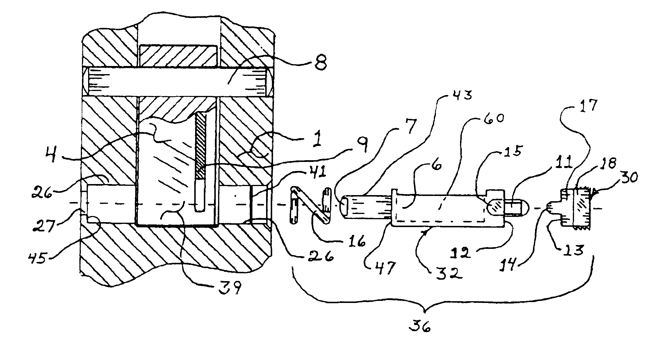
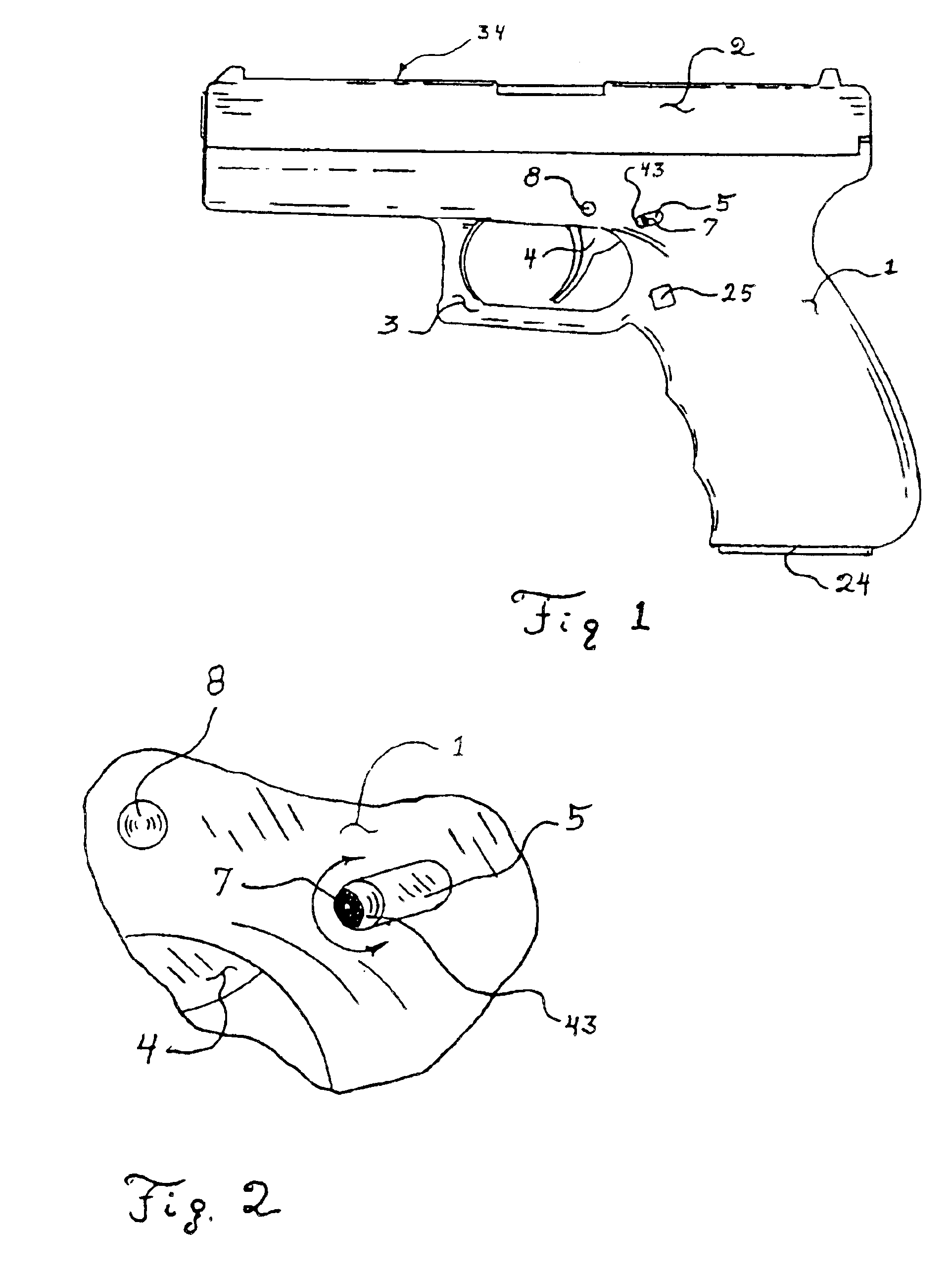
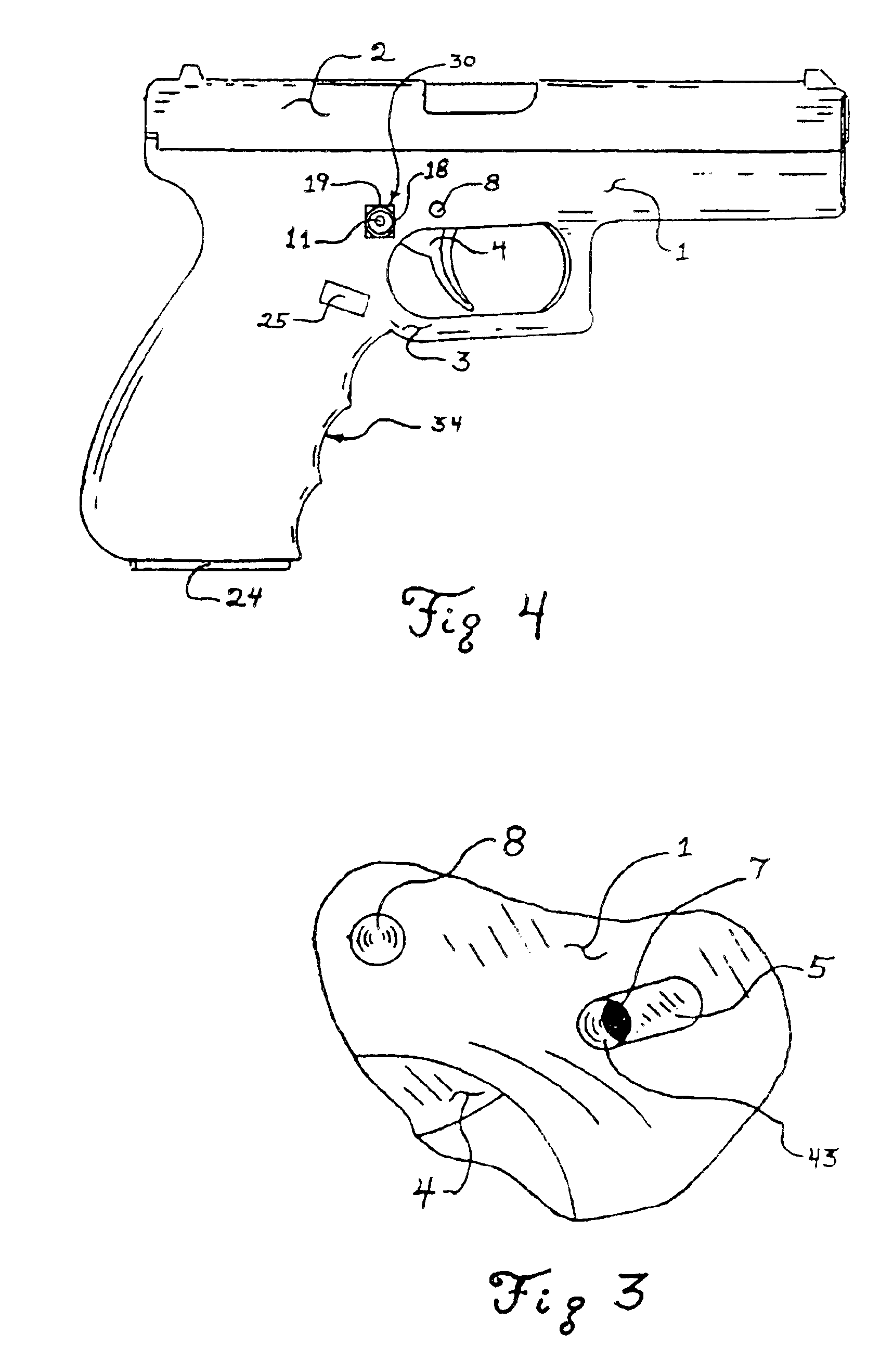
Another embodiment of the trigger lock 36 is shown in FIGS. 15 & 16. In this embodiment, a thumb lever 50 is attached to the rod 56 of the shaft 32 with a pin 54 or other attachment method. The lever 50 and the shaft 32 can be reversed for the right hand or left hand user. FIG. 15 shows the lever 50 positioned on the left side of the handgun 34 for the right handed user.

The shaft 32 rotates relative to the frame 1 when the user engages the thumb pad 52 on the end of thumb lever 50. Rotating the thumb lever 50 causes the shaft 32 and cutout 60 to rotate. In one position of the thumb lever 50 and thumb pad 52, as shown in FIG. 15, the trigger 4 and triggering linkage 9 can clear the cutout 60 when the trigger 4 is pulled. In this position, the trigger will operate. Rotating the thumb lever 50 towards the butt end of the handgun 34, causes the shaft 32 to rotate such that cutout 60 is positioned where the trigger 4 and triggering linkage 9 cannot move and engage the shaft 32. The handg...


PUM


Abstract

A trigger lock is shown which rotates from a fire position in which the trigger can operate and to a no-fire position in which the trigger cannot operate. The lock is located primarily within the frame. A thumb lever or a key can be used to engage the trigger lock to rotate the trigger lock from the fire to the no-fire position and vice versa.

Description

FIELDThe present version of this invention relates generally to the field of devices used to deter the use of weapons by those unauthorized to use them by preventing the trigger from firing.BACKGROUNDThis invention relates to devices to deter the use of weapons by those unauthorized to use them, and more particularly to devices that engage a trigger of a weapon or device to deter the weapon or device from operation unless the operator has the key to allow the trigger of the weapon or device to operate.Weapons such as handguns, rifles, shotguns, cross-bows and others generally are activated or fired by using a trigger. The trigger generally operates with various linkages that interact with elements of the weapon causing the weapon to fire. The operation of the weapon trigger largely depends on the type of weapon. There can be a danger if someone unauthorized to operate the weapon gains access to the weapon and is able to “fire” the weapon especially if the weapon is loaded.Devices ot...

Claims


Application Information

Patent Timeline
Patent Type & Authority Patents(United States)
IPC IPC(8): F41A17/00F41A17/52F41A17/02
CPCF41A17/52F41A17/02F41A17/46
Inventor DOIRON, GERALD J.
Owner DOIRON GERALD J
Why Eureka
Try Eureka