Drive assembly for acoustic sources

a technology of acoustic sources and drive assemblies, which is applied in the direction of seismic energy generation, instruments, seismicity, etc., can solve the problems of system mechanical impedance, low frequency spectrum efficiency of the system, and the inability of the vibrational system to give perfect control of the sour

Inactive Publication Date: 2005-02-08
PGS AMERICA INC
View PDF12 Cites 36 Cited by
  • Summary
  • Abstract
  • Description
  • Claims
  • Application Information

AI Technical Summary

Problems solved by technology

But today, even though it has proven to be very successful, vibroseis could hardly claim to give perfect control over the source, or even to know exactly what the power spectrum is at the source.
Both conventional hydraulic and electrodynamic vibrator designs have a fundamental problem re

Method used


Image

  • Drive assembly for acoustic sources
  • Drive assembly for acoustic sources
  • Drive assembly for acoustic sources

Examples


Embodiment Construction

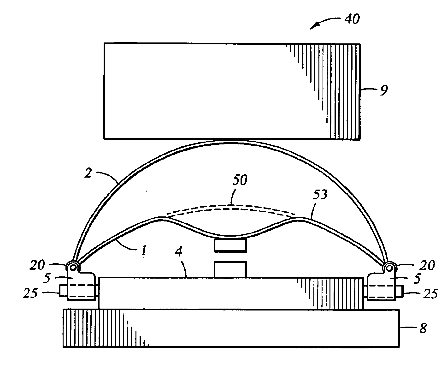
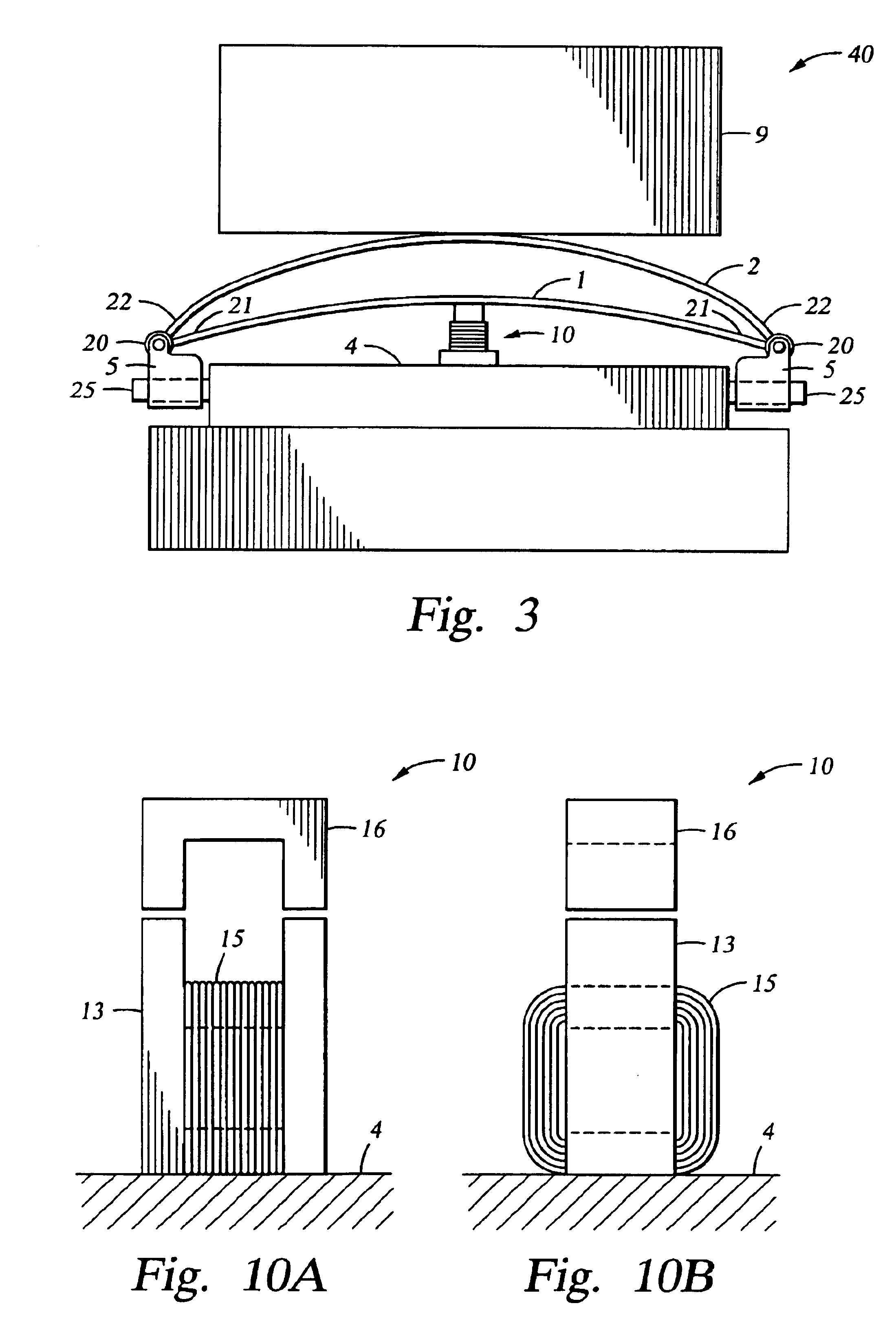
In one example embodiment of the present invention, a drive assembly for a seismic land vibrator is provided. As illustrated in FIGS. 3-8, the drive assembly comprises at least a first spring element 1, which operates in at least two vibration modes in a seismic frequency band of interest. In various embodiments of the present invention, the first spring element 1 is caused to operate in two vibration modes in both single spring embodiments and plural spring embodiments. To teach the broad aspect of the present invention, examples of plural spring embodiments are described first. After describing the plural spring embodiments, the generalized single spring embodiments will be more easily understood.

In one plural spring embodiment, as illustrated in FIG. 3, the drive assembly 40 comprises a first spring element 1, and second spring element 2, a baseplate 8, a driver 10, and a reaction mass 9. The driver 10 is in communication with the first spring element 1. The first spring element ...


PUM


Abstract

In one embodiment of the present invention, a drive assembly for a seismic land vibrator is provided. The drive assembly comprises at least a first spring element. The first spring element operates in at least two vibration modes in a seismic frequency band of interest. The drive assembly also comprises a baseplate, a driver, and a reaction mass. The driver interacts with the reaction mass and the first spring element to transfer energy to the baseplate.

Description

BACKGROUND OF THE INVENTIONThe vibroseis system is an engineered system that commonly uses hydraulically operated vibrators to send continuous acoustic signals (instead of shock-waves) through the earth. The vibroseis signal is normally a swept-frequency sinusoid (called a “sweep”). In general, the sweep is from 3 to 24 seconds, but any length is possible. A vibroseis field recording is then converted into a “conventional” seismogram by the cross-correlation of each trace of the vibroseis field record with the transmitted sweep. The principle of vibroseis is well known in the art and is presented, for example, in W. E. Liang, Appendix B: History and Early Development of the Vibroseis System of Seismic Exploration, VIBROSEIS, 749-765, GEOPHYSICS REPRINT SERIES NO. 11 (1989), incorporated herein by reference.When vibroseis was first released, it was thought to be the means of perfect control over the spectrum of the seismic wavelet. But today, even though it has proven to be very succ...

Claims


Application Information

Patent Timeline
IPC IPC(8): G01V1/155G01V1/02
CPCG01V1/155
Inventor TENGHAMN, STIG RUNE LENNART
Owner PGS AMERICA INC
Why Eureka
Try Eureka