
Method and apparatus for generating a desired three-dimensional digital model of an orthodontic structure

a digital model and orthodontic technology, applied in the field of orthodontics, can solve the problems of human inability to accurately develop a visual three-dimensional image of an orthodontic structure, manual application of such bends, and inability to accurately estimate three-dimensional wire bends

Inactive Publication Date: 2005-02-08
ORAMETRIX
View PDF29 Cites 63 Cited by
  • Summary
  • Abstract
  • Description
  • Claims
  • Application Information

AI Technical Summary

Problems solved by technology

Unfortunately, in the oral environment, it is impossible for a human being to accurately develop a visual three-dimensional image of an orthodontic structure due to the limitations of human sight and the physical structure of a human mouth.
In addition, it is humanly impossible to accurately estimate three-dimensional wire bends (with an accuracy within a few degrees) and to manually apply such bends to a wire.
Further, it is humanly impossible to determine an ideal bracket location to achieve the desired orthodontic structure based on the mental images.
It is also extremely difficult to manually place brackets in what is estimated to be the ideal location.
As a result of multiple wire changes, patient discomfort is increased as well as the cost.
Unfortunately, the current innovations to change the practice of orthodontic from an art to a science have only made limited progress.
As such, the tooth will not be repositioned to the desired location.
Another issue with the brackets being the focal point is that once the brackets are placed on the teeth, they are generally fixed for the entire treatment.
For example, misplacement of a bracket, misapplication of a bend in the wire, loss or attrition of a bracket, bonding failure, the patient falls outside of the “normal” patient model (e.g., poor growth, anatomical constraints, etc.), patient lack of cooperation in use of auxiliary appliance, etc. are factors in delayed treatment results.
Another issue with the brackets being the focal point is that customized brackets are expensive.
While the milling process is very accurate, some of the accuracy is lost by tumble polishing.
Further accuracy is lost in that the placement of the brackets on the teeth and installation of the wire are imprecise operations.
As is known, a slight misplacement of one bracket changes the force on multiple teeth and hinders treatment.
Such an installation jig is also expensive.
Thus, such scientific orthodontic treatment is expensive and has many inherent inaccuracies.

Method used


Image

  • Method and apparatus for generating a desired three-dimensional digital model of an orthodontic structure
  • Method and apparatus for generating a desired three-dimensional digital model of an orthodontic structure
  • Method and apparatus for generating a desired three-dimensional digital model of an orthodontic structure

Examples


Embodiment Construction

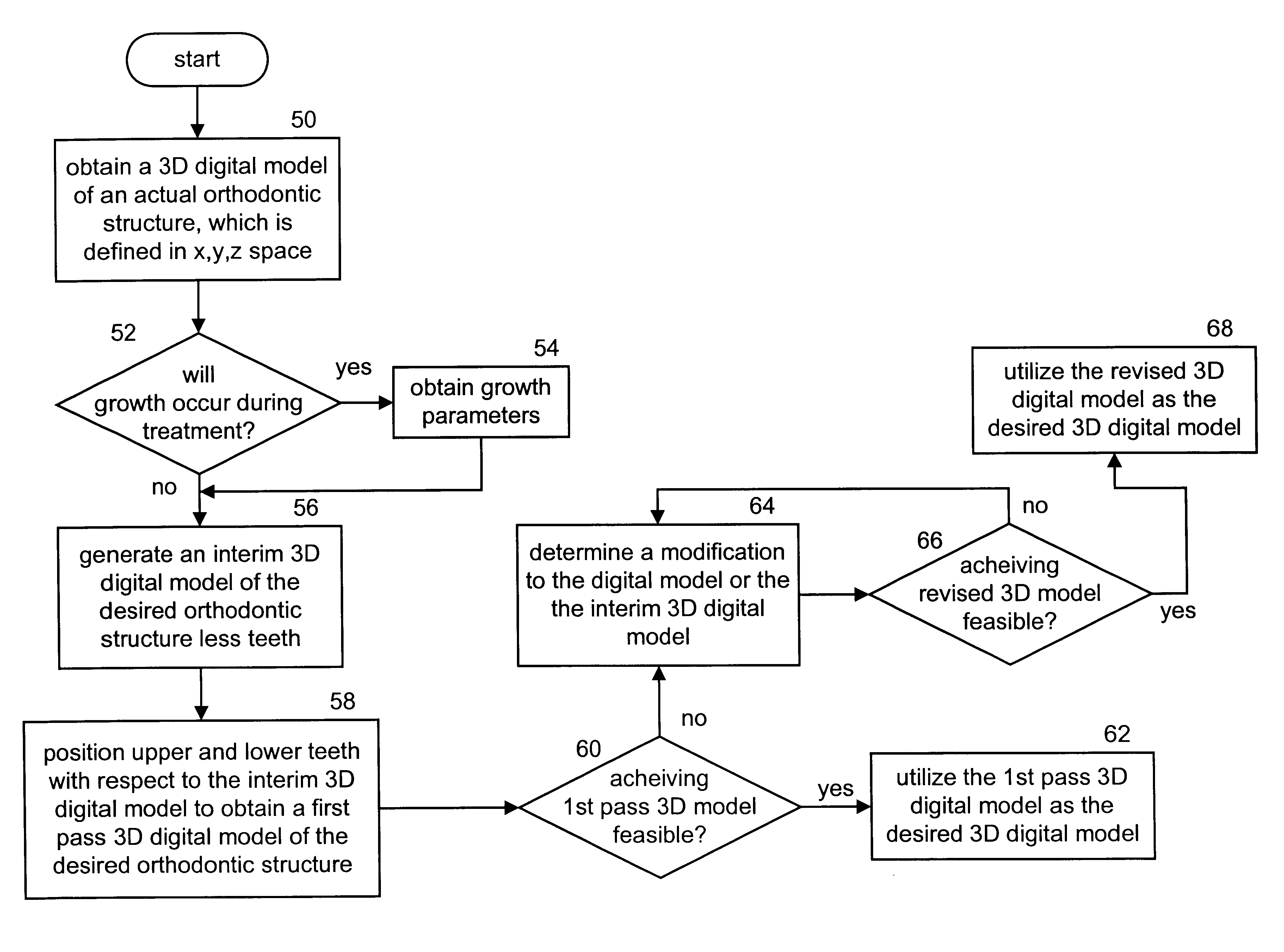
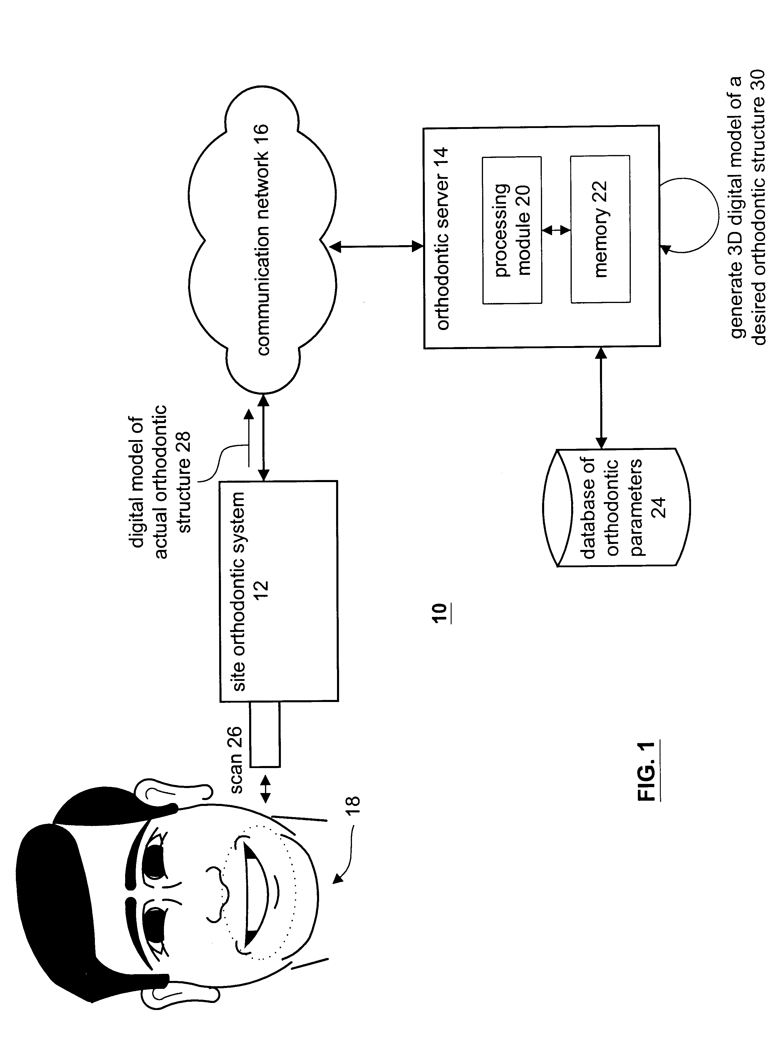
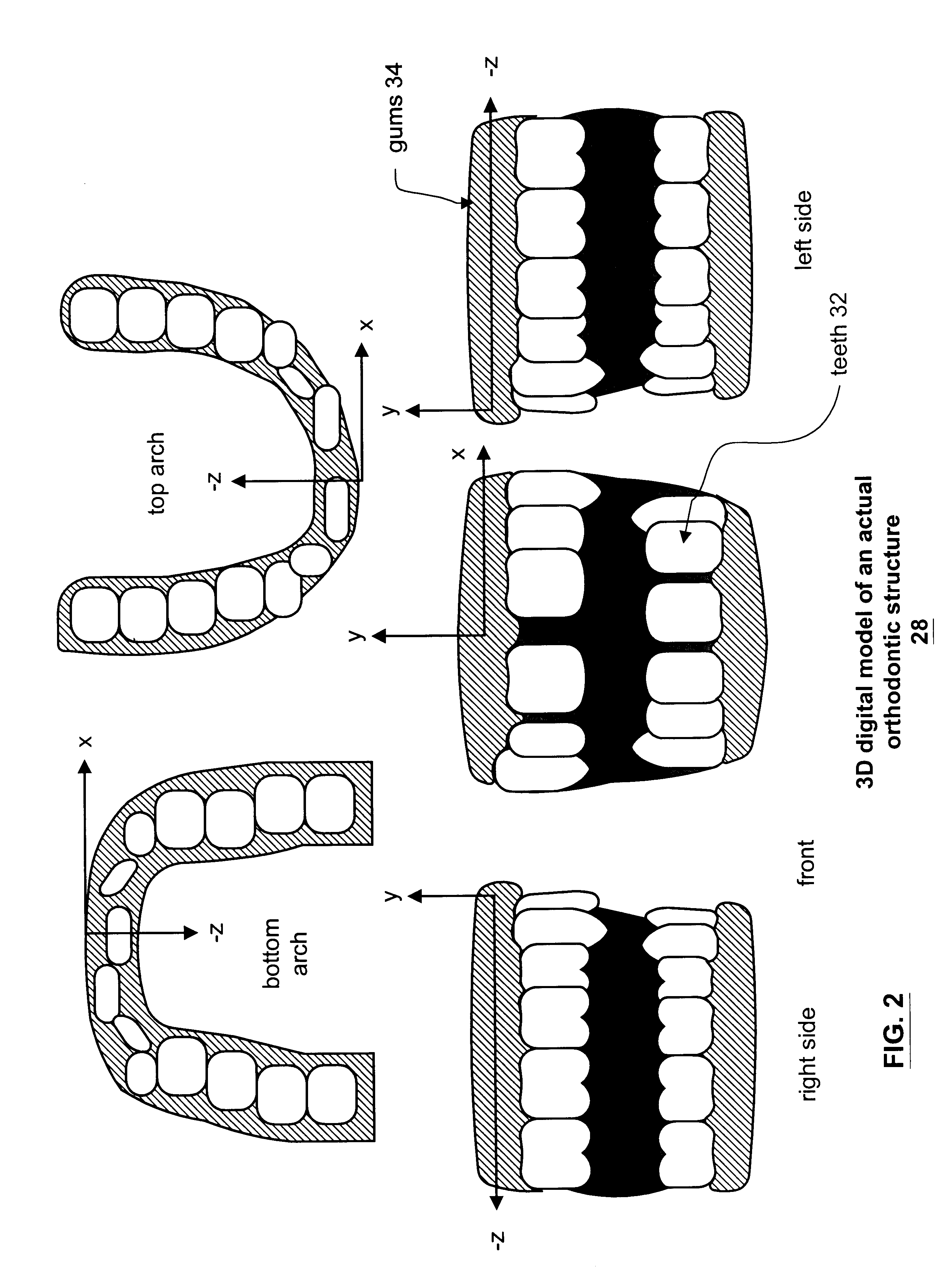
Generally, the present invention provides a method and apparatus for generating a three-dimensional digital model of a desired orthodontic structure. Such a method and apparatus include processing that begins by obtaining a three-dimensional model of an actual orthodontic structure, wherein the three-dimensional digital model is defined in x, y, z space. The processing then continues by generating an interim three-dimensional model of the desired orthodontic structure less teeth. The interim three-dimensional model is designed in x, y, z space and includes the desired placement of an occlusal plane, an upper-arch form, a lower-arch form, an upper-arch midline, and a lower-arch midline. The processing then continues by positioning the upper and lower teeth with respect to the interim digital model and the defined x, y, z space to obtain a first pass three-dimensional digital model of the desired orthodontic structure. The processing continues by determining whether achieving the firs...


PUM


Abstract

A method and apparatus for generating a three-dimensional digital model of a desired orthodontic structure include processing that begins by obtaining a three-dimensional model of an actual orthodontic structure, wherein the three-dimensional digital model is defined in x, y, z space. The processing then continues by generating an interim three-dimensional model of the desired orthodontic structure less teeth. The interim three-dimensional model is designed in x, y, z space and includes the desired placement of an occlusal plane, an upper-arch form, a lower-arch form, an upper-arch midline, and a lower-arch midline. The processing then continues by positioning the upper and lower teeth with respect to the interim digital model and the defined x, y, z space to obtain a first pass three-dimensional digital model of the desired orthodontic structure. The processing continues by determining whether achieving the first pass three-dimensional model is feasible. When achieving the first pass three-dimensional image is feasible, the processing continues by utilizing the first pass three-dimensional model as the desired three-dimensional digital model.

Description

TECHNICAL FIELD OF THE INVENTIONThis invention relates generally to the practice of orthodontics and in particular to a method and apparatus for treating an orthodontic patient.BACKGROUND OF THE INVENTIONOrthodontics is the practice of manipulating a patient's teeth to provide better function and appearance. In general, brackets are bonded to a patient's teeth and coupled together with an arched wire. The combination of the brackets and wire provide a force on the teeth causing them to move. Once the teeth have moved to a desired location and are held in a place for a certain period of time, the body adapts bone and tissue to maintain the teeth in the desired location. To further assist in retaining the teeth in the desired location, a patient may be fitted with a retainer.To achieve tooth movement, orthodontists utilize their expertise to first determine a three-dimensional mental image of the patient's physical orthodontic structure and a three-dimensional mental image of a desire...

Claims


Application Information

Patent Timeline
Patent Type & Authority Patents(United States)
IPC IPC(8): A61C7/00G06T17/00A61C9/00
CPCA61C7/00G06T17/00A61C9/004A61C7/002A61C9/0046
Inventor SACHDEVA, ROHITRUBBERT, RUDGER
Owner ORAMETRIX
Learn More