Two-stage charging device

a charging device and two-stage technology, applied in electric vehicles, electric power, transportation and packaging, etc., can solve the problems of low efficiency of linear voltage regulators, unfavorable miniaturization of circuits, and complicated circuit design, and achieve the effect of reducing the output power

Inactive Publication Date: 2005-02-08
QUANTA COMPUTER INC
View PDF4 Cites 9 Cited by
  • Summary
  • Abstract
  • Description
  • Claims
  • Application Information

AI Technical Summary

Benefits of technology

The two-stage charging device includes a power supply and a battery module wherein the battery module is equipped with a linear charging device, a controller and a battery. During the charging process, the controller determines the difference between a main supply voltage provided by the power supply and the voltage of the battery, and outputs an adjusting signal to the power supply according to the obtained voltage difference. The power supply device then adjusts the main supply voltage according to the adjusting signal to maintain the voltage difference between the main supply voltage and the battery voltage approximately at a pre-set voltage level. The battery voltage will increase along with the passing of the charging time. When the voltage difference between the main supply voltage and the battery voltage is smaller than a lower voltage level, the controller will raise up the voltage level of the adjusting signal. Conversely, when the voltage difference between the main supply voltage and the battery voltage is larger than an upper voltage level, the controller will reduce the voltage level of the adjusting signal so as to cause the power supply device to reduce its output power. Therefore, by appropriately adjusting the main supply voltage according to the level of the adjusting signal, the main supply voltage can be maintained at a voltage level slightly above the battery voltage.

Problems solved by technology

The design of a notebook computer, for example, not only needs to be compact, but also requires considerations about the battery duration and heat dissipation problems.
How to miniaturize the product and at the same time reduce its heat dissipation thus becomes an important issue.
Despite having the advantage of a simple circuit design, the linear voltage regulator has a low efficiency when the voltage difference between the input voltage and the output voltage is large.
In contrast to the linear voltage regulator, the switching voltage regulator, despite having a higher efficiency, has a complicated circuit design which is unfavorable for the miniaturization of the circuit.
However, charging efficiency may be significantly reduced when the transistor Q consumes a large amount of energy because of large difference between the main supply voltage Vs and the battery voltage Vb.

Method used


Image

  • Two-stage charging device
  • Two-stage charging device
  • Two-stage charging device

Examples


Embodiment Construction

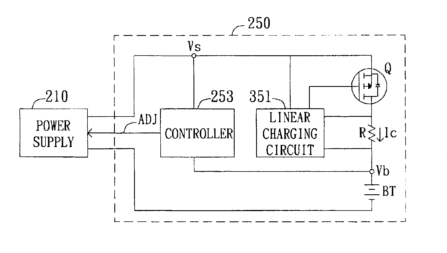
The main concept of the invention is to integrate a charging circuit into a battery module. If a linear voltage regulator is adopted, a large amount of heat will be generated inside the battery module when the voltage difference between the supply voltage and the battery voltage is too large. On the other hand, if a switching voltage regulator is adopted, its complicated circuit design is unfavorable to the design of miniaturization. Moreover, a switching voltage regulator also generates a certain amount of heat during its operation and requires a certain space of room for heat dissipation. Therefore, the switching voltage regulator has only limited benefits but is unfavorable in terms of miniaturization when integrated into a battery module.

The invention aims to resolve the heat dissipation problem encountered when a linear voltage regulator is integrated into a battery module. The details of the embodiment are disclosed below.

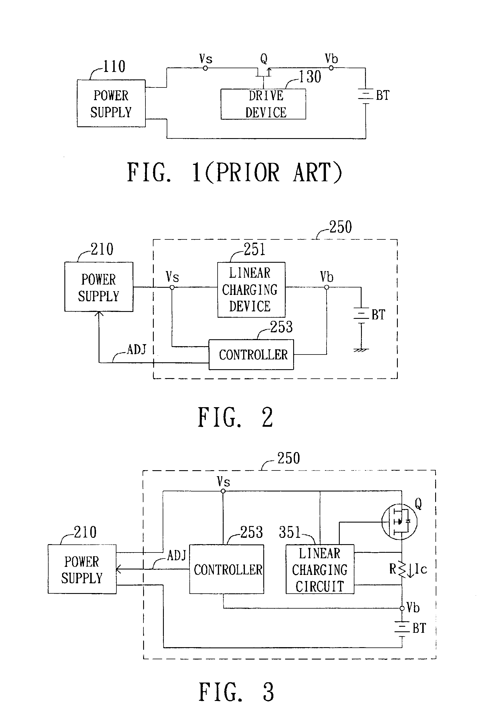
In the conventional practice, the linear charging devic...


PUM


Abstract

A two-stage charging device including a power supply device and a battery module is provided. The battery module is equipped with a linear charging device, a controller and a battery. During the charging process, the controller determines the voltage difference between the main supply voltage provided by the power supply device and the battery voltage, and then outputs an adjusting signal to the power supply device according to the obtained voltage difference. Then the power supply device adjusts the supply voltage according to the adjusting signal to maintain the voltage difference between the supply voltage and the battery voltage approximately at a pre-set voltage level. The battery voltage will rise along with the passing of the charging time. If the voltage difference between the main supply voltage and the battery voltage is smaller than a lower voltage level, the controller will increase the voltage level of the adjusting signal so as to increase the power supplied by the power supply device. Conversely, if the voltage difference between the supply voltage and the battery voltage is larger than an upper voltage level, the controller will reduce the voltage level of the adjusting signal to enable power supply device to reduce the power supplied by the power supply device. Therefore, by making appropriate adjustments according to the level of the adjusting signal, the main supply voltage can be maintained at a voltage level slightly above the battery voltage.

Description

This application claims the benefit of Taiwan application Serial No. 091135136, filed on Dec. 4, 2002.BACKGROUND OF THE INVENTION1. Field of the InventionThe invention relates in general to a charging device, and more particularly to a two-stage charging device.2. Description of the Related ArtIn order to make the electronic products more compact and light, developers are searching for a breakthrough in the design of portable electronic devices. The design of a notebook computer, for example, not only needs to be compact, but also requires considerations about the battery duration and heat dissipation problems. How to miniaturize the product and at the same time reduce its heat dissipation thus becomes an important issue.Portable electronic devices normally use batteries as the power supply; and the rechargeable battery module is normally adopted. The design of a charging device is particularly important when both the efficiency and the stability of power supply are considered. The ...

Claims


Application Information

Patent Timeline
Patent Type & Authority Patents(United States)
IPC IPC(8): H02J7/00
CPCH02J7/0077H02J7/00712
Inventor CHEN, SENG-FENG
Owner QUANTA COMPUTER INC
Why Eureka
Try Eureka