Removable louver and tilt control

a technology of tilt control and louver, which is applied in the direction of movable grilles, shutters/movable grilles, construction, etc., can solve the problems of needing to disassemble shutter frames, and achieve the effect of maintaining the privacy of building occupants

Inactive Publication Date: 2005-02-15
BLACHLEY DAVID
View PDF22 Cites 34 Cited by
  • Summary
  • Abstract
  • Description
  • Claims
  • Application Information

AI Technical Summary

Problems solved by technology

A disadvantage of a shutter 100 is that louver tilt control utilizes a tilt bar that is located within the shutter frame 110, 120 field-of-view.
Another disadvantage of the shutter 100 is that shutter frame disassembly is needed to replace a damaged louver 130.

Method used


Image

  • Removable louver and tilt control
  • Removable louver and tilt control
  • Removable louver and tilt control

Examples


Embodiment Construction

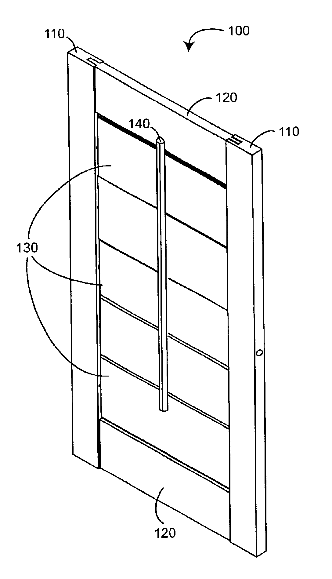
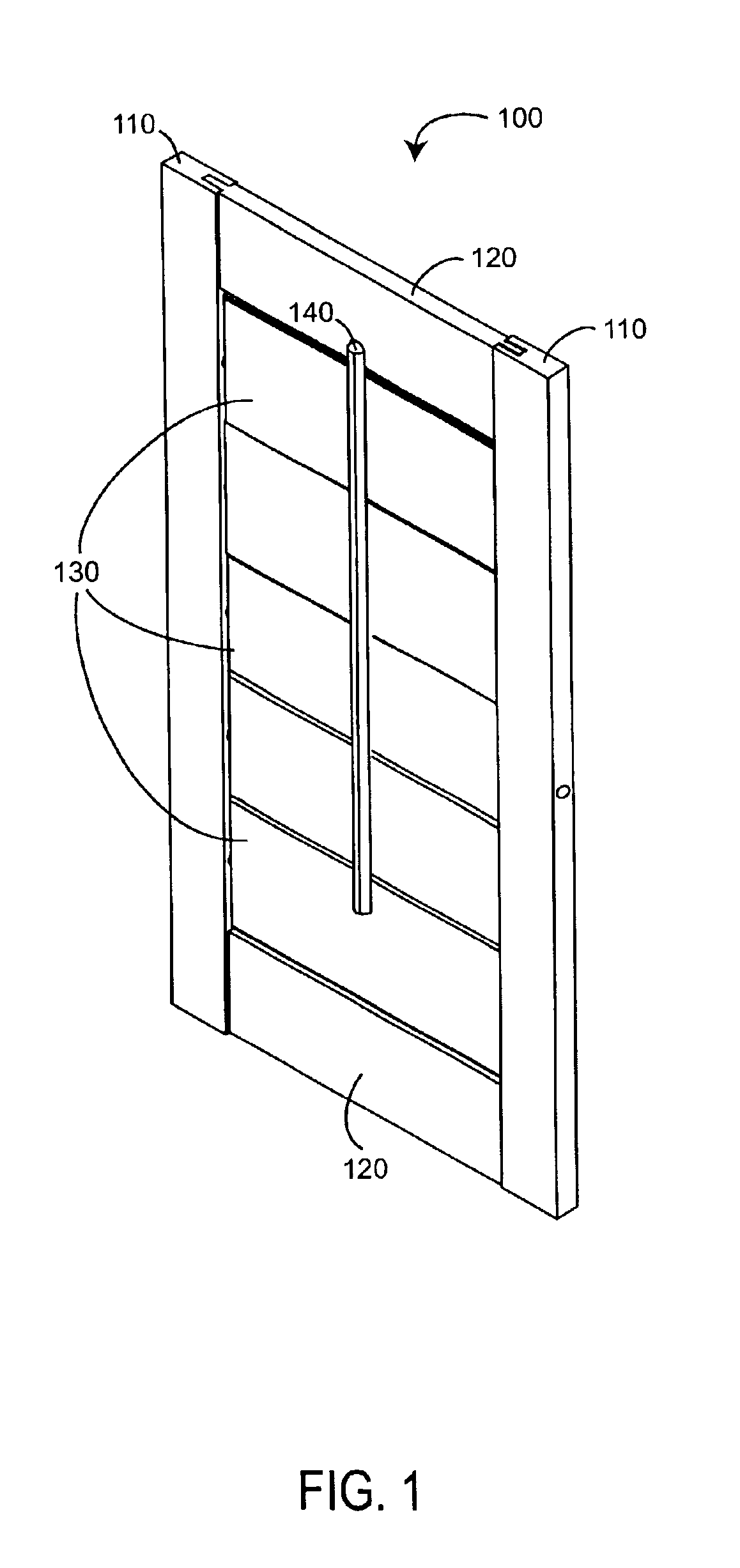
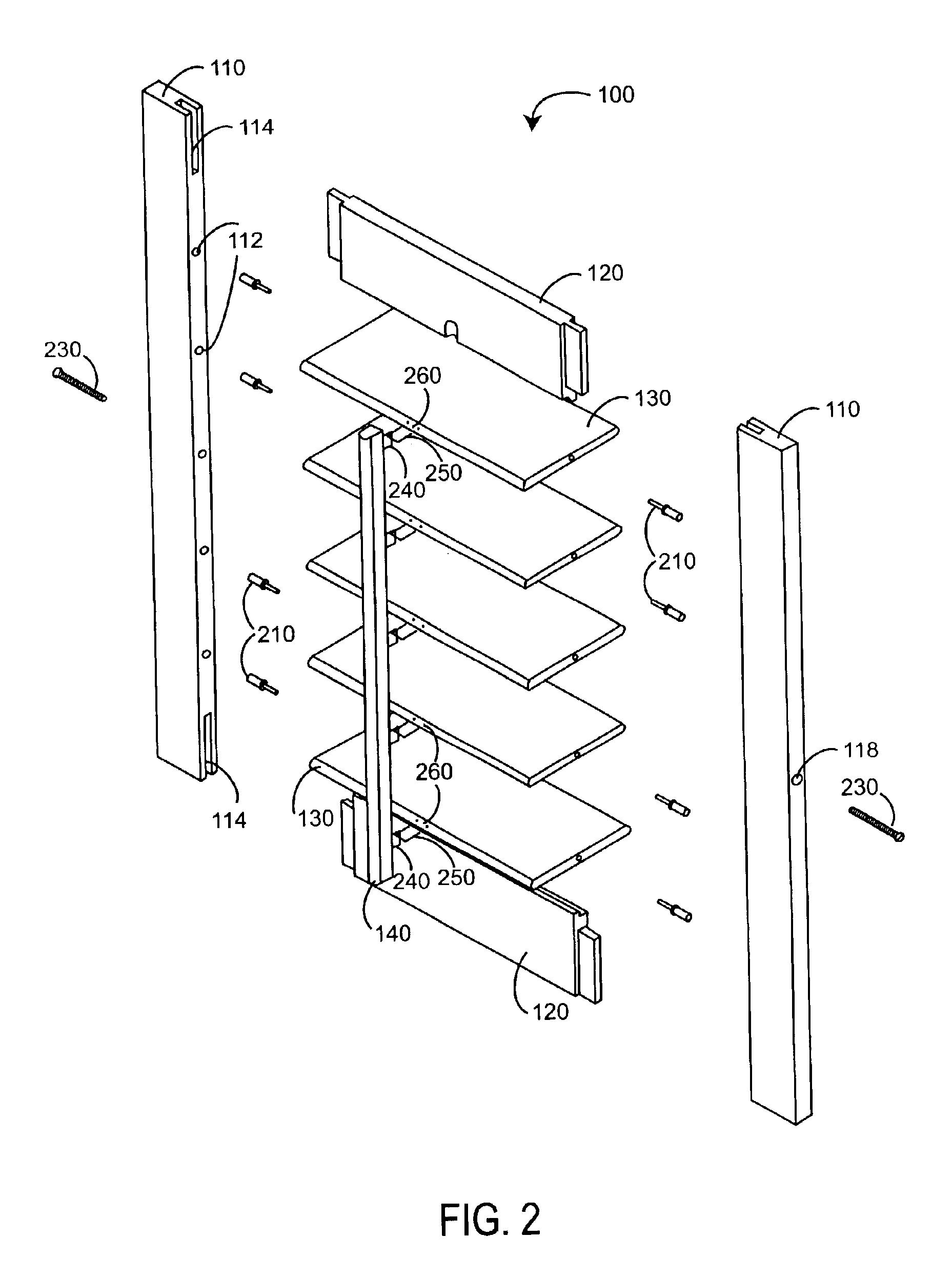
FIG. 3 illustrates a shutter 300 having full groove stiles 310, spreaders 320, stile inserts 330, segmented link bars 340, and louver end caps 350, 360. The segmented link bars 340 advantageously eliminate the need for a tilt bar 140 (FIGS. 1-2), clearing the field-of-view. The louver end caps 350 advantageously provide for removable louvers 370, which allow the repair or replacement of broken or damaged louvers without disassembly of the shutter frame 310, 320 and ease louver cleaning. The full groove stile 310 has an end to end groove 312, which can be cut in a single manufacturing step across several stiles as compared with end-proximate partial grooves 114 (FIG. 2). The end-to-end groove 312 accommodates a stile insert 330 that includes pin holes 332, which eliminates the manufacturing steps required for drilling pin holes 112 (FIG. 2) along the stile 110 (FIG. 2). A louver end cap 350 is adapted to removably retain a louver 370. A snap-fit stile button 352 is adapted to press f...


PUM


Abstract

A tilt control is adapted to rotate a louver between at least a partially open position and a partially closed position within a shutter frame. The tilt control comprises a stile adapted as a portion of the shutter frame and a gear rotatably retained within the stile. A rack slideably retained within the stile. The gear engages the rack so that linear movement of the rack causes a corresponding rotation of the gear. The louver removably connected to the gear so that rotation of the gear rotates the louver.

Description

BACKGROUND OF THE INVENTIONShutters are a high quality interior window treatment, having a combination of style, functionality and elegance that sets them apart from other window coverings. Shutters provide warmth in the winter and protect from damaging heat and sunlight in the summer. Shutters also provide complete control of view, privacy and light.SUMMARY OF THE INVENTIONFIGS. 1-2 illustrate a shutter 100 having stiles 110, spreaders 120, louvers 140 and a tilt bar 140. As shown in FIG. 1, the shutter 100 is installable within a window opening and operable to control the amount of light entering a building interior and to maintain the privacy of the building occupants, in a manner that is well known in the art. The stiles 110 are attached to the spreaders 120 so as to form a shutter frame having a generally rectangular opening. The louvers 130 are rotatably mounted to the stiles 110 within the frame. The tilt bar 140 is linked to the leading edges of the, louvers 130 and operable...

Claims


Application Information

Patent Timeline
Patent Type & Authority Patents(United States)
IPC IPC(8): E06B9/02E06B7/096E06B7/02
CPCE06B9/02E06B7/096
Inventor BLACHLEY, DAVID
Owner BLACHLEY DAVID
Why Eureka
Try Eureka