Unlock instant, AI-driven research and patent intelligence for your innovation.
Lead propelling device
What is Al technical title?
Al technical title is built by PatSnap Al team. It summarizes the technical point description of the patent document.
a propelling device and lead technology, applied in the direction of propelling pencils, printing, writing implements, etc., can solve the problems of affecting the stability of the projection length
Inactive Publication Date: 2005-02-15
MITSUBISHI PENCIL CO LTD
View PDF3 Cites 9 Cited by
Summary
Abstract
Description
Claims
Application Information
AI Technical Summary
This helps you quickly interpret patents by identifying the three key elements:
Problems solved by technology
Method used
Benefits of technology
Benefits of technology
[0039]The invention is devised to solve the problems of lead breakage and excessive propelling of the lead by knocking unknowingly while writing, and it is hence an object thereof to present a lead propelling device capable of projecting a lead by a predetermined length from the leading end of the writing tool by knocking operation, and maintaining the projected lead by the predetermined length if knocking operation is repeated, and more particularly a lead propelling device stable in lead projecting length, easy to recognize the leading end, easy to use, and free from risk of biting by the gripping part of the chuck even in the case of a fine lead.
[0041]In this manner, in the lead propelling device of the invention, since the timing of gripping and releasing the lead by the lead gripping mechanism is defined by the distance to the parts interlocking with the knock operation, the lead can be projected by a predetermined length, and the projecting length can be stabilized.
[0044]Therefore, the lead projecting length is stable. If the lead is fine, rigidity is maintained between the slider for projecting the lead and the lead gripping mechanism, and misalignment is prevented. Besides, in order that the leading end may be easily recognized visually while writing, the leading end of the writing tool is tapered and thin.
[0046]Even if this lead propelling device, the lead can be projected by a predetermined length, and the projection length can be stable.
Problems solved by technology
If forgetting to knock, the lead is worn up to the front end of the leading end pipe 132, and writing may be scratchy, or finally the writing paper may be torn by the front end of the rigid leading end pipe.
On the other hand, if knocked more than necessary to propel the lead, the projected lead may be too long, and the lead is often broken.
That is, by sliding resistance between members or other factor, the expanding timing of the chuck 153 may be delayed, and the lead projecting extent may not be stable.
In this writing lead holder, members very difficult to machine are used, which is also a bottleneck for realizing this proposal.
For example, as for the shaft tube 151, aside from forming a taper hole 152 at the leading end, through-holes 151a (see FIG. 38) for pass-through of the support arm 159 of the stopper 160 must be formed at two positions, and this shape is very difficult to process, the productivity is poor, and it is predicted to be a very expensive component.
The stopper 160 is formed integrally in the support arm 159 but such support arm is very difficult to process, the productivity is poor, and it is predicted to be a very expensive component.
It is also difficult to assemble the writing lead holder.
Method used
Image
Click on the blue label to locate the original text in one second.
Reading with bidirectional positioning of images and text.
Examples
first embodiment
[0087]Embodiments are described below with reference to the accompanying drawings. FIGS. 1 to 16 show a lead propelling device in the invention.
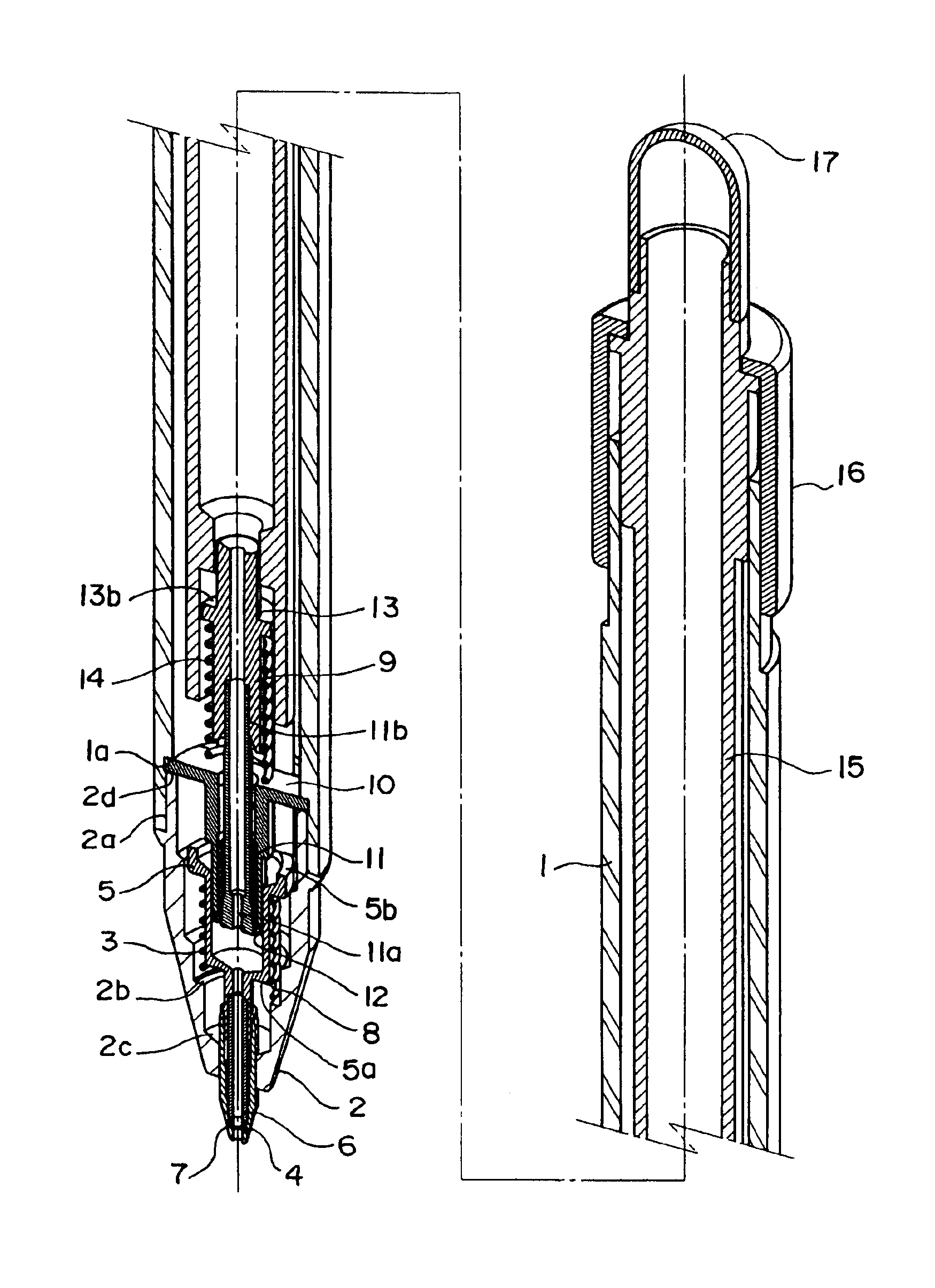
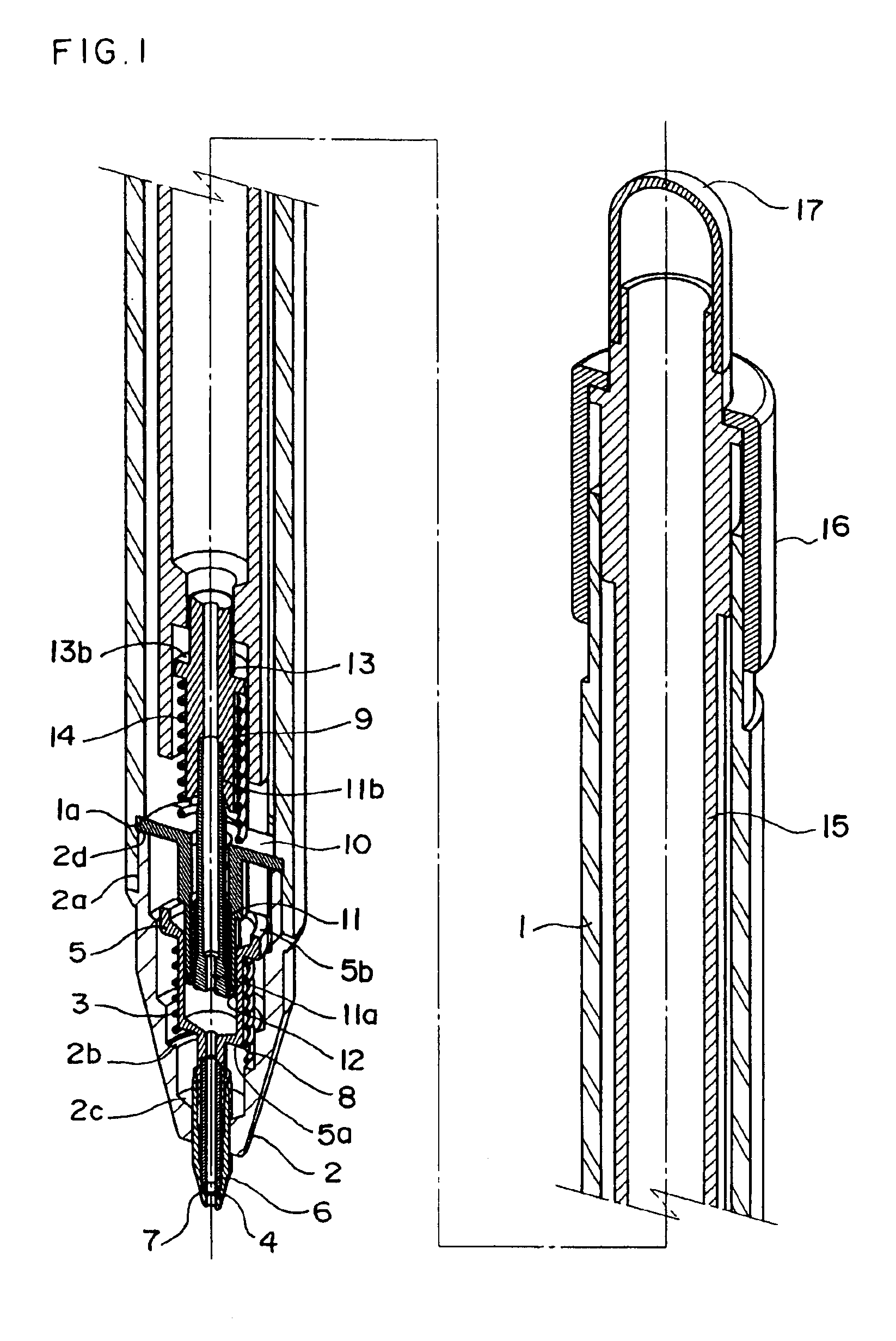
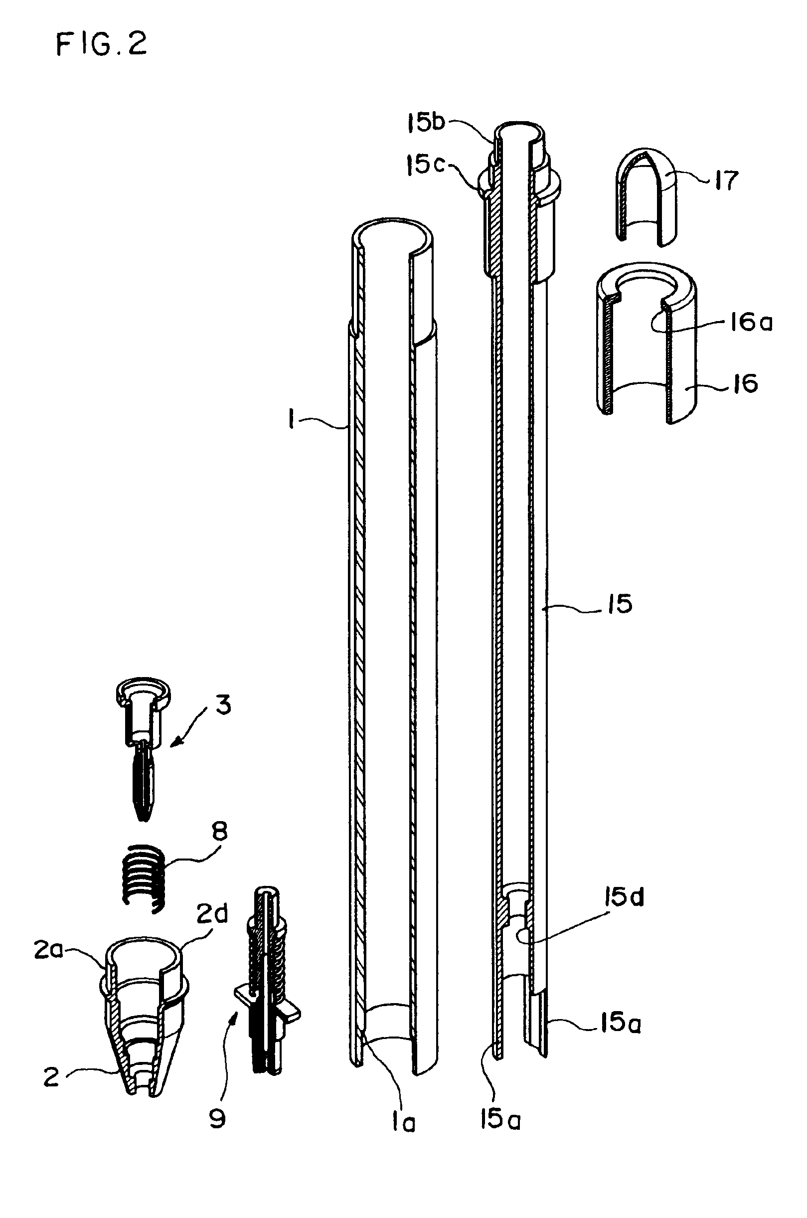
[0088]A mechanical pencil in the first embodiment comprises, as shown in FIGS. 1 and 2, a shaft tube 1, a tip 2, a slider 3, a lead gripping mechanism 9, a lead case 15, a knock cover 17, other components and component units. The configuration of the first embodiment is explained below, first relating to the component units of the lead gripping mechanism 9 and slider 3.
[0089]The lead gripping mechanism 9 is explained. As shown in FIG. 3, the lead gripping mechanism 9 includes a fixing tube 10, a chuck 11, a chuck spring 14, and a chuck joint 13.
[0090]The fixing tube 10 has a guide surface 10a of cylindrical shape of which both sides are cropped flatly, and a fine end tube 10b is formed at the front end. A tightening ring 12 is press-fitted and fixed as tightening part in the inner hole of the end tube 10b.
[0091]The tightening ring 12 is mad...
second embodiment
[0151]In the lead propelling device in the second embodiment, as shown in FIG. 18, a circular protrusion or circular step 51a is formed in the front inner wall of the inner hole of the shaft tube 51.
[0152]The lead gripping mechanism 79 is inserted from the front side of the shaft tube 51, and the rear end of the fixing tube 58 is abutted and fixed to the front part of the step 51a. In succession, the link unit 80 is inserted from the front end of the shaft tube 51. At this time, the inner side of the leg 57c of the link 57 is inserted oppositely to the flat guide surface 58a of the fixing tube 58.
[0153]The lead case 64 is a long tubular body as shown in FIG. 18, having a shaft 64d for detachably fixing the knock cover 68 at its rear end, and a flange 64f is formed slightly ahead. Flat parts 64a are formed at two positions approximately from the front end to near the front end of the tubular body along the periphery, and a further short flat part 64b is formed across a step 64e.
[015...
PUM
Abstract
The lead propelling device of the invention is a lead propelling device having a structure for gripping and releasing the lead by a lead gripping mechanism by knocking operation, not transmitting the knocking force to the lead gripping mechanism in knock forward operation, wherein a stopper not allowing the lead to pass by its own weight interlocks with the knock operation, the lead abuts against the stopper rear end upon release of the lead, the lead is inserted into the stopper after gripping the lead in knock backward operation, thereby propelling the lead, and therefore after the knock operation part advances by a predetermined distance, the lead gripping mechanism clears gripping of the lead, and when the lead gripping mechanism grips the lead in the backward stroke of the knock operation part, the knock operation part is set to be movable backward further by a predetermined distance.
Description
BACKGROUND OF THE INVENTION[0002]1. Field of the Invention[0003]The present invention relates to a lead propelling device capable of projecting a lead by a predetermined length from the leading end of the writing tool by knocking operation, and maintaining the projected lead by the predetermined length if knocking operation is repeated, and more particularly to an improvement of lead propelling device used in mechanical pencil, writing lead holder, or the like.[0004]2. Description of the Related Art[0005]A structure of a hitherto well-known mechanical pencil is shown in FIG. 36, and it is explained according to the drawing.[0006]As shown in FIG. 36, a chuck 125 is provided at a front portion of a shaft tube 123 by way of a shaft joint 124, and a tightening tool 126 is fitted on the outer periphery of gripping part of this chuck 125. A biased chuck spring 128 is provided between a lead case 127 affixed to the rear end of the chuck 125 and the shaft joint 124. By this chuck spring 128...
Claims
Application Information
Patent Timeline
Application Date:The date an application was filed.
Publication Date:The date a patent or application was officially published.
First Publication Date:The earliest publication date of a patent with the same application number.
Issue Date:Publication date of the patent grant document.
PCT Entry Date:The Entry date of PCT National Phase.
Estimated Expiry Date:The statutory expiry date of a patent right according to the Patent Law, and it is the longest term of protection that the patent right can achieve without the termination of the patent right due to other reasons(Term extension factor has been taken into account ).
Invalid Date:Actual expiry date is based on effective date or publication date of legal transaction data of invalid patent.
