Hydraulic swage press

a swage press and hydraulic technology, applied in forging presses, manufacturing tools, forging hammers, etc., can solve problems such as frusto-conical surfaces, “depth” of assembly, and configuration strain

Inactive Publication Date: 2005-02-22
BETASWAGE
View PDF9 Cites 8 Cited by
  • Summary
  • Abstract
  • Description
  • Claims
  • Application Information

AI Technical Summary

Benefits of technology

The objective of the present invention is to provide an improved swaging press that retains the manufacturing, cost and size advantages of cone type swaging presses while achieving performance capabilities similar to scissor type machines.

Problems solved by technology

The product may typically be made of steel and may be of cylindrical form but this is not necessarily the case.
Some disadvantages of the cone design include the “depth” of the assembly and the strain in the configuration due to mis-matching curvature of the frusto-conical surface in the piston and the part frusto-conical surfaces on the co-operating die shoes.
This mis-matching of curvatures causes bearing to actually occur only along a line where the curves actually match which means, under load, that the conical surfaces actually distort and there is a significant impingement of varying degrees depending on load and relative piston position.
As the actual measurement of the final swage diameter is made at the piston, accuracy suffers as well.
The bearing load at this point is extreme and many machines of this type seize under load without significant amounts of lubrication.
A significant disadvantage is, however, that it has a high manufacturing cost due mainly to the 1:1 mechanical gain (i.e. 1 mm of piston movement=1 mm change in swaging diameter) whereas the cone type may have as much as 3:1 mechanical gain.
The disadvantages of this design include that it is difficult to manufacture and the configuration, under radial load, results in the shoes tending to slide to the corners of the octagonal cone as this represents the outer most reactive low energy position.
Any wear in the guides will create irregular swaging action.
Many of these machines cost more in die tooling than in the actual cost of the swage press itself.

Method used


Image

  • Hydraulic swage press
  • Hydraulic swage press
  • Hydraulic swage press

Examples


Embodiment Construction

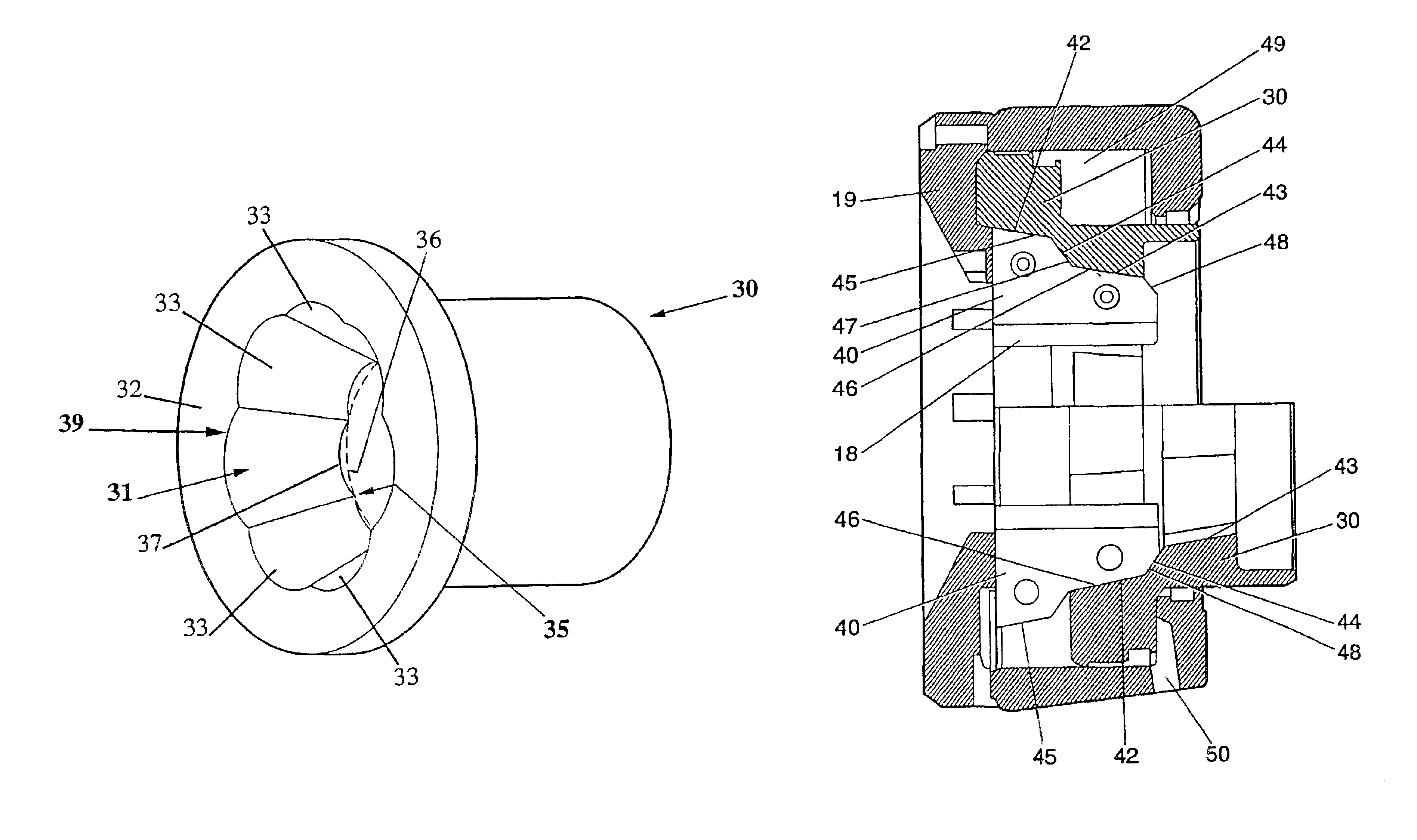
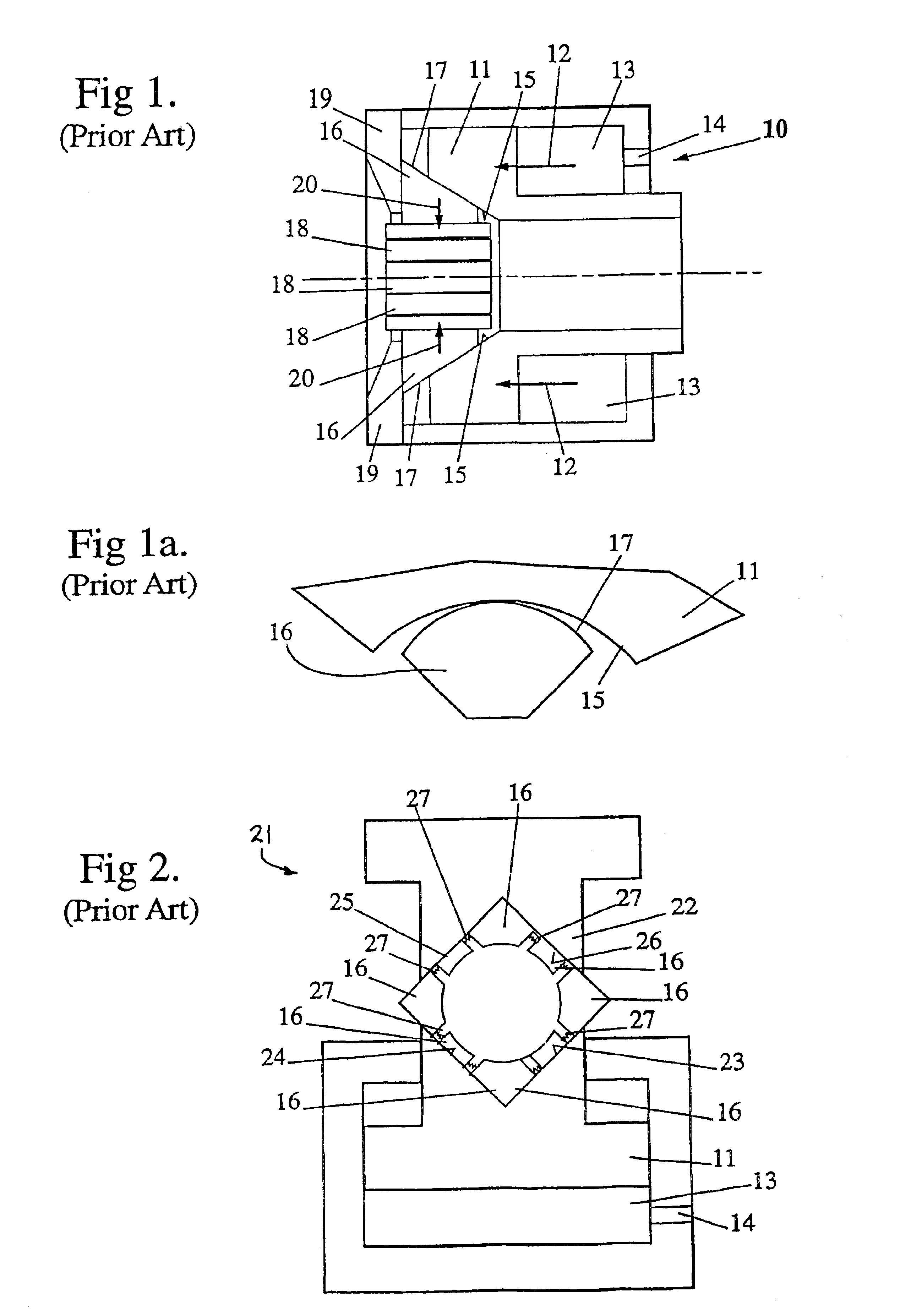
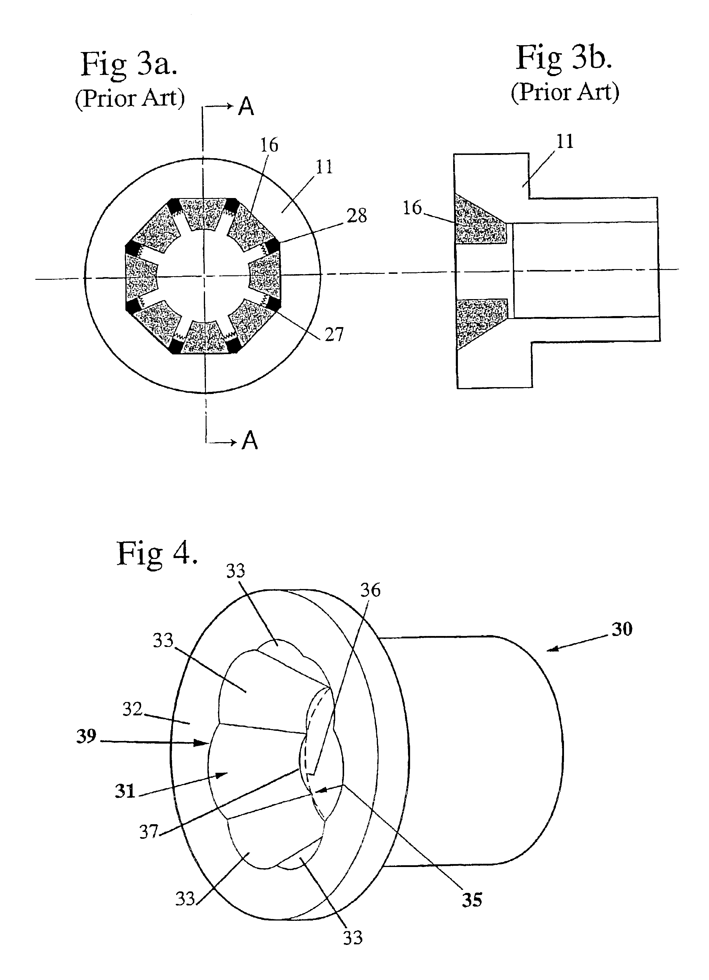
Referring first to FIGS. 1 and 1a, a conventional form of cone type swage press 10 is schematically illustrated employing an operational piston 11 driven in a forward direction 12 by pressurised hydraulic fluid entering chamber 13 via port 14. The forward end face of the piston 11 is recessed to form a frusto-conical surface 15 which co-operably engages with part frusto-conical surfaces 17 on the shoe members 16, each said member 16 carrying a die 18 facing inwardly. The die shoes 16 are restrained against forward movement by an end wall 19 of the press assembly whereby the shoes move inwardly as shown by direction arrows 20 when the piston 11 moves in a forward direction 12. As shown in FIG. 1a, the bearing contact region between the die shoes 16 and the frusto-conical surface 15 of the piston 11 is essentially a line resulting from the method of manufacturing same. As a result a reasonably long bearing area is required resulting in turn in a press assembly that is relatively long ...


PUM

PropertyMeasurementUnit
diameteraaaaaaaaaa
axial lengthaaaaaaaaaa
radius of curvatureaaaaaaaaaa

Abstract

The present specification discloses a swaging press including a piston member co-operable with a plurality of die shoes to drive the die shoes inwardly upon axial movement of the piston member during a swaging operation, the piston member having a frusto-conical recessed region divided into a plurality of circumferentially disposed bearing surface zone of a defined axial length, each of the bearing surface zones having an inner axial end with a numerical radius of curvature less than or equal to the radius of curvature of a circular line forming the lateral edges of each of the bearing surface zones at the inner axial end whereby at least 50% of the outer bearing surface of each said die shoe remains in bearing engagement with the adjacent said bearing surface zone over the axial movement of the piston member during a swaging operation.

Description

FIELD OF THE INVENTIONBACKGROUND OF THE INVENTIONThe present invention relates to an improved hydraulic swage press.Hydraulic swage presses are machines that with an array of suitable tooling called “dies”, are able to reduce a product from one diameter to a smaller diameter in a cold state. The product may typically be made of steel and may be of cylindrical form but this is not necessarily the case. In the fluid power connector sector, particularly the previously described “product” is called a ferrule and is used to connect a hose to hose end. Ferrule type connectors are of course also used in other industries, however, increasing demands in the fluid power sector, such as increasing pressure and longer endurance levels, mean that ferrules in that industry are required to do more work and, as a result, higher performance of the swage press is continually sought.One conventional form of swage press design can generally be described as the “cone” type. This type of swage press util...

Claims


Application Information

Patent Timeline
Patent Type & Authority Patents(United States)
IPC IPC(8): B21J13/02B21J9/00B21J9/06B21D39/04B21J5/06
CPCB21D39/046B21J13/025B21J9/06Y10T29/5367
Inventor ESSEN, FRED VAN
Owner BETASWAGE
Why Eureka
Try Eureka