Spinning reel having cover for decoration

a spinning reel and decoration technology, applied in the field of spinning reels, can solve the problem of still bolt head exposed

Inactive Publication Date: 2005-02-22
OKUMA FISHING TACKLE
View PDF14 Cites 28 Cited by
  • Summary
  • Abstract
  • Description
  • Claims
  • Application Information

AI Technical Summary

Benefits of technology

The primary objective of the present invention is to provide a spinning

Problems solved by technology

However, the cover is mounted on the reel body by bolt

Method used


Image

  • Spinning reel having cover for decoration
  • Spinning reel having cover for decoration
  • Spinning reel having cover for decoration

Examples


Embodiment Construction

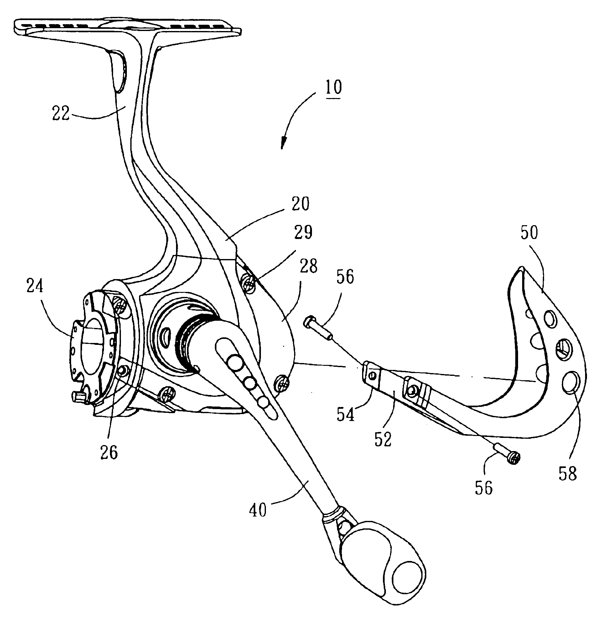
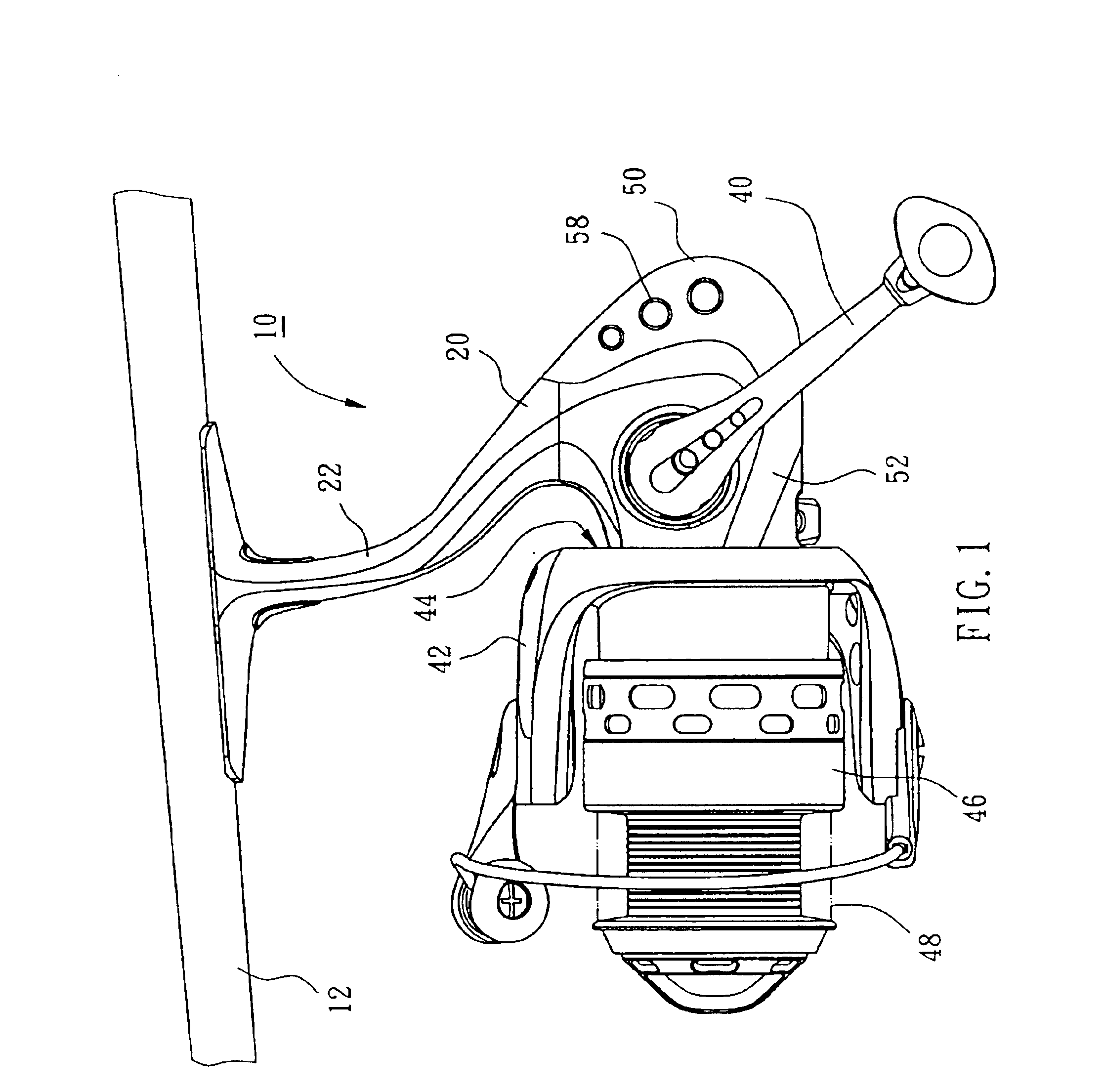
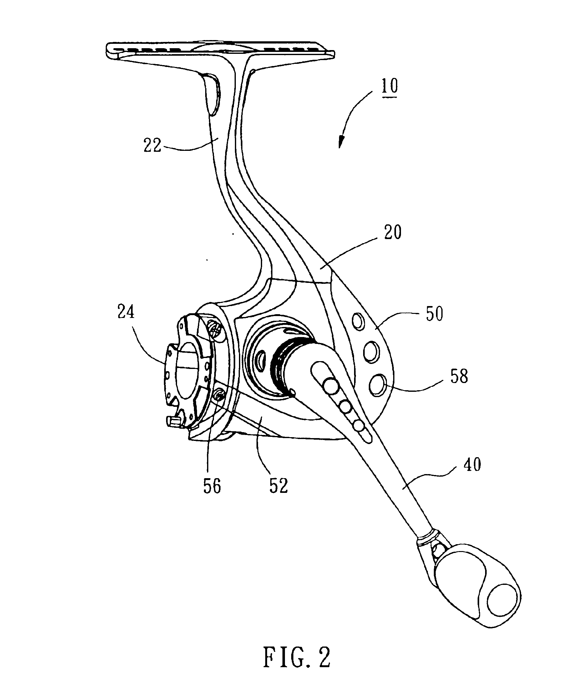
As shown in FIGS. 1-3, a spinning reel 10 of the first preferred embodiment of the present invention mainly comprises a reel body 20, a handle 40 rotatably mounted on the reel body 20, a rotor 42 provided on the reel body 20 to be driven by the handle 40 for rotation, a spool 46 provided on the reel body 20 to be driven by the handle 40 for reciprocation, and a cover 50.

The reel body 20 has a connection portion 22, an engagement portion 24 and a lowland portion 28. The connection portion 22 is a T-shaped post to be coupled with a fishing rod 12. The lowland portion 28 is arranged at a rear of the reel body 20 and has a shape that is complementary to the cover 50. The engagement portion 24 is a short column at a front of the reel body 20 having two thread holes 26 on a periphery thereof. Bolts 29 are screwed on the lowland portion 28 to fix a drive mechanism (not shown) and the other parts of the spinning reel 10 in the reel body 20.

The handle 40 is rotatably mounted on the reel body...


PUM


Abstract

A spinning reel includes a reel body having a connection portion for connecting said reel body to a fishing rod, and an engagement portion. A handle is rotatably mounted on the reel body. A rotor has a hole fitted onto the engagement portion of the reel body to mask the engagement portion. A spool is rotatably mounted on the reel body for a fishing line wound thereon. A cover is mounted on the reel body to mask a portion of the reel body on which heads of bolts are exposed. The cover has two arms each of which have a distal end coupled to the engagement portion.

Description

BACKGROUND OF THE INVENTION1. Field of the InventionThe present invention relates generally to a fishing tool, and more particularly to a spinning reel, which has a cover mounted thereon for decoration and for masking the exposed bolts.2. Description of the Related ArtA conventional spinning reel has a reel body, a drive mechanism mounted inside the reel body, a handle to drive the drive mechanism working, a rotor rotatably mounted on the reel body and driven by the drive mechanism for rotation, and a spool reciprocally mounted on the reel body and driven by the drive mechanism for reciprocation. The drive mechanism is fixedly mounted in the reel body by bolts and the reel body consists of two cases coupled with each other by bolts too, so that the spinning reel has many heads of the bolts exposed outside. The conventional spinning reel was provided with a cover mounted on the reel body for masking the exposed heads of the bolts. However, the cover is mounted on the reel body by bol...

Claims


Application Information

Patent Timeline
IPC IPC(8): A01K89/01A01K89/00
CPCA01K89/01
Inventor CHANG, LIANG-JEN
Owner OKUMA FISHING TACKLE
Why Eureka
Try Eureka