Magnetic resistance system for a roller-type bicycle trainer

Inactive Publication Date: 2005-02-22
SARIS EQUIP LLC
View PDF4 Cites 61 Cited by
  • Summary
  • Abstract
  • Description
  • Claims
  • Application Information

AI Technical Summary

Benefits of technology

The magnetic resistance arrangement may be in the form of a magnet mounting member that is interconnected with the frame of the roller, and is radially spaced outwardly from one of the rollers. The mounting member extends across the surface of the roller, and includes spaced apart magnets that are located radially outwardly from the surface of the roller. The mounting member is preferably interconnected with the frame of the roller-type trainer via an adjustment

Problems solved by technology

The user is thus unable to increase the resistance beyond that which is provided by the f

Method used


Image

  • Magnetic resistance system for a roller-type bicycle trainer
  • Magnetic resistance system for a roller-type bicycle trainer
  • Magnetic resistance system for a roller-type bicycle trainer

Examples


Embodiment Construction

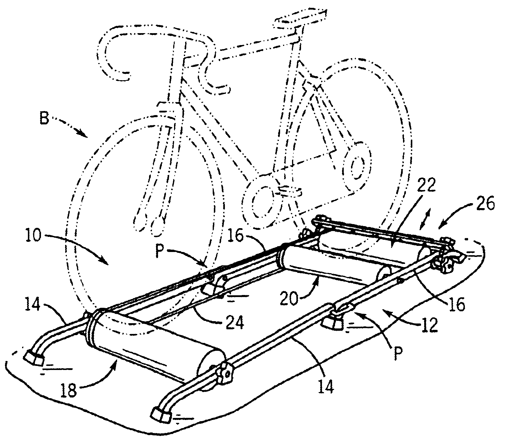
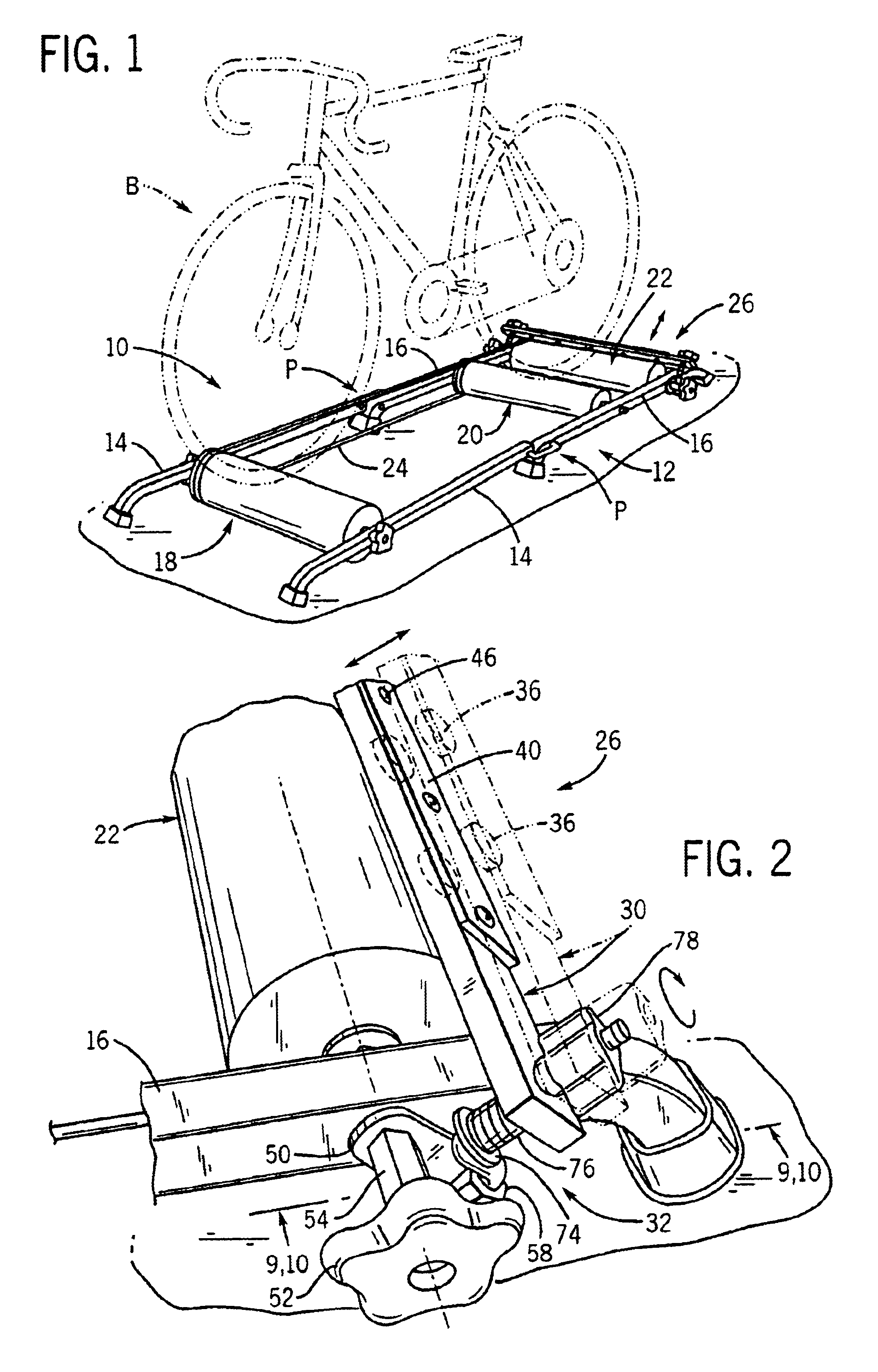
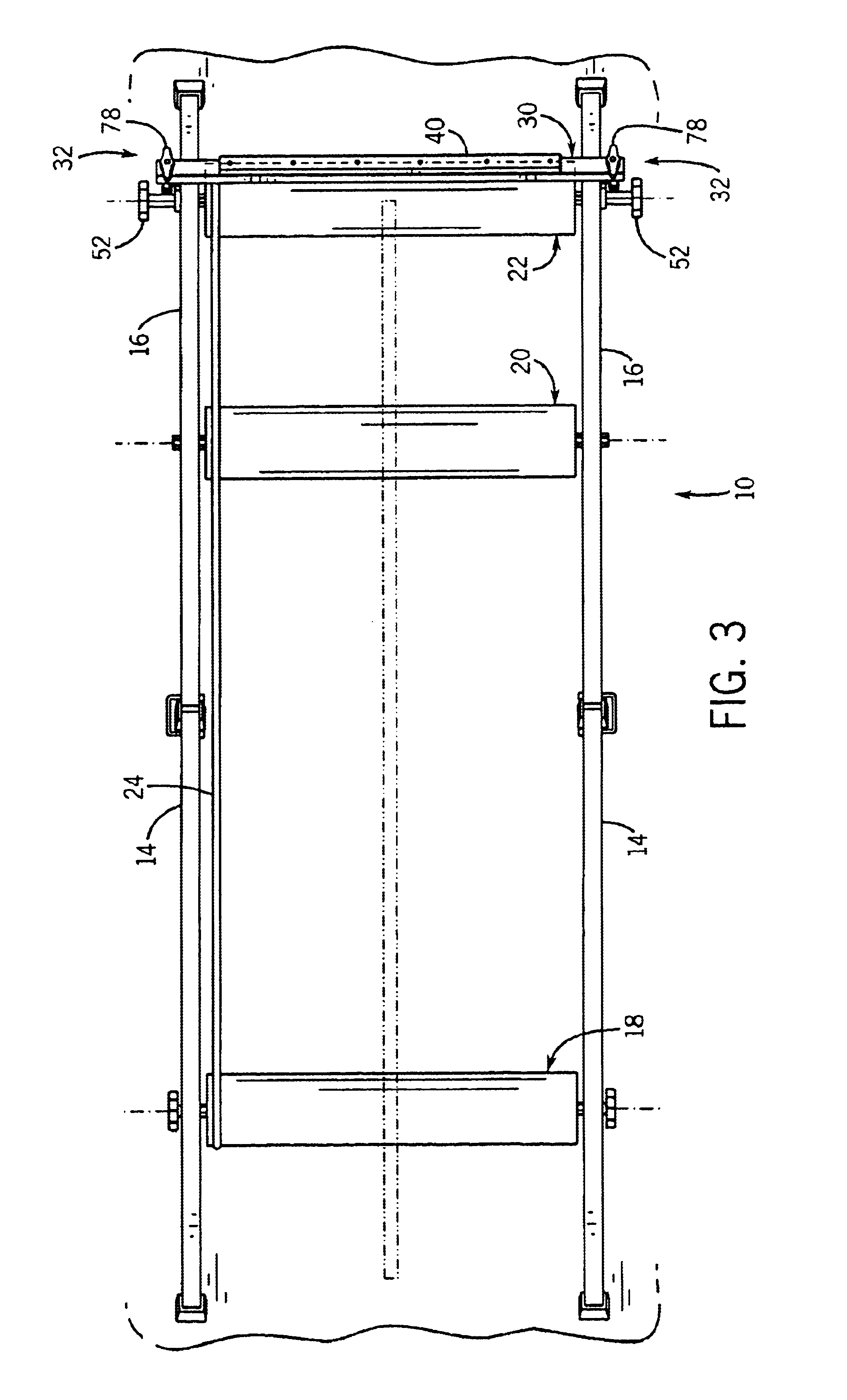
As shown in FIGS. 1-3, a roller-type stationary bicycle trainer 10 includes a frame 12 having a pair of spaced apart front rails 14 and a pair of spaced apart rear rails 16. Front rails 14 and rear rails 16 are joined together by a pivot connection P, to enable trainer 10 to fold for storage. A series of cylindrical rollers extend between rails 14 and 16. The rollers include a front roller 18 and a pair of rear rollers 20, 22. In a known manner, the driven wheel of a bicycle B is adapted to be placed between rear rollers 20, 22 and the front wheel of bicycle B is adapted to be placed on front roller 18.

The illustrated construction of frame 12 is known in the art. It is understood that the illustrated construction of frame 12 is representative of any type of support frame which may be employed to support rollers 18-22, and that any other satisfactory frame construction may be employed.

In a manner as is known, a user pedals bicycle B so as to rotate the driven wheel of bicycle B, whic...


PUM


Abstract

A roller-type bicycle trainer includes a frame and a series of rollers that are configured to support the wheels of the bicycle. At least one of the rollers is formed of electrically conductive material, e.g. aluminum, and a magnetic resistance arrangement includes one or more magnets that are spaced from the electrically conductive material in order to create an eddy current resistive force that resists rotation of the roller, upon rotation of the roller by operation of the bicycle. The magnetic resistance arrangement includes an adjustment feature for adjusting the position of the one or more magnets relative to the roller, to vary the strength of the eddy current resistive force and thereby the degree of resistance to rotation of the bicycle wheel.

Description

BACKGROUND AND SUMMARY OF THE INVENTIONThis invention relates to bicycle trainers, and more particularly to a stationary roller-type bicycle trainer having a resistance feature.A roller-type bicycle trainer has a series of rollers that support the front and rear wheels of a bicycle. The user pedals the bicycle while maintaining the bicycle upright, to simulate the manner in which the bicycle is ridden outdoors. Typically, a single roller supports the front or non-driven wheel of the bicycle, and the rear or driven wheel of the bicycle is supported by a pair of rollers. The rear wheel rotates in response to operation of the bicycle pedals, which imparts rotation to the rollers with which the rear wheel is engaged. Rotation of one of the rear rollers is transferred to the front roller by means of a belt that extends between and is engaged with the rear roller and the front roller.In a typical roller-type bicycle trainer, the only resistance to rotation of the bicycle wheels is provide...

Claims


Application Information

Patent Timeline
IPC IPC(8): A63B69/16A63B21/005
CPCA63B21/0051A63B69/16A63B2069/168A63B2069/167
Inventor KOLDA, CLINT D.COLAN, PETER V.
Owner SARIS EQUIP LLC
Why Eureka
Try Eureka