
Wire rewinding box with recharge unit

a recharge unit and wire rewinding box technology, which is applied in the direction of cable arrangements between relatively moving parts, machines/engines, and arrangements using take-up reels/drums, etc., can solve the problems of limiting the application of conventional models, unable to maintain a specified length outside the box, and big trouble for users

Inactive Publication Date: 2005-02-22
LIAO SHENG HSIN
View PDF24 Cites 41 Cited by
  • Summary
  • Abstract
  • Description
  • Claims
  • Application Information

AI Technical Summary

Benefits of technology

The primary objective of the invention is to provide a wire rewinding box with a recharge unit, which has the conventional function of a wire rewinding box to rewind a communication wire. In addition to that, the user can also pull on the communication wire to enable the recharge unit to generate power. Optionally, the user can press on a press handle to enable the recharge unit to generate power. Thereby, providing functions of power generating, power recharging and providing a power source, the rewinding box can be connected to a mobile phone set or such communication appliances for recharging purpose and providing power source.

Problems solved by technology

When the communication wire is pulled out of a conventional rewinding box, it may become tense because it is subjected to the powerful pulling force of the coil spring, resulting in failure of maintaining a specified length outside the box.
It could cause big trouble to the user.
However, the conventional wire rewinding box has only the function of rewinding the communication wire, without the functions of recharging and supply power source.
Therefore, the conventional models are restricted in their applications.

Method used


Image

  • Wire rewinding box with recharge unit
  • Wire rewinding box with recharge unit
  • Wire rewinding box with recharge unit

Examples


Embodiment Construction

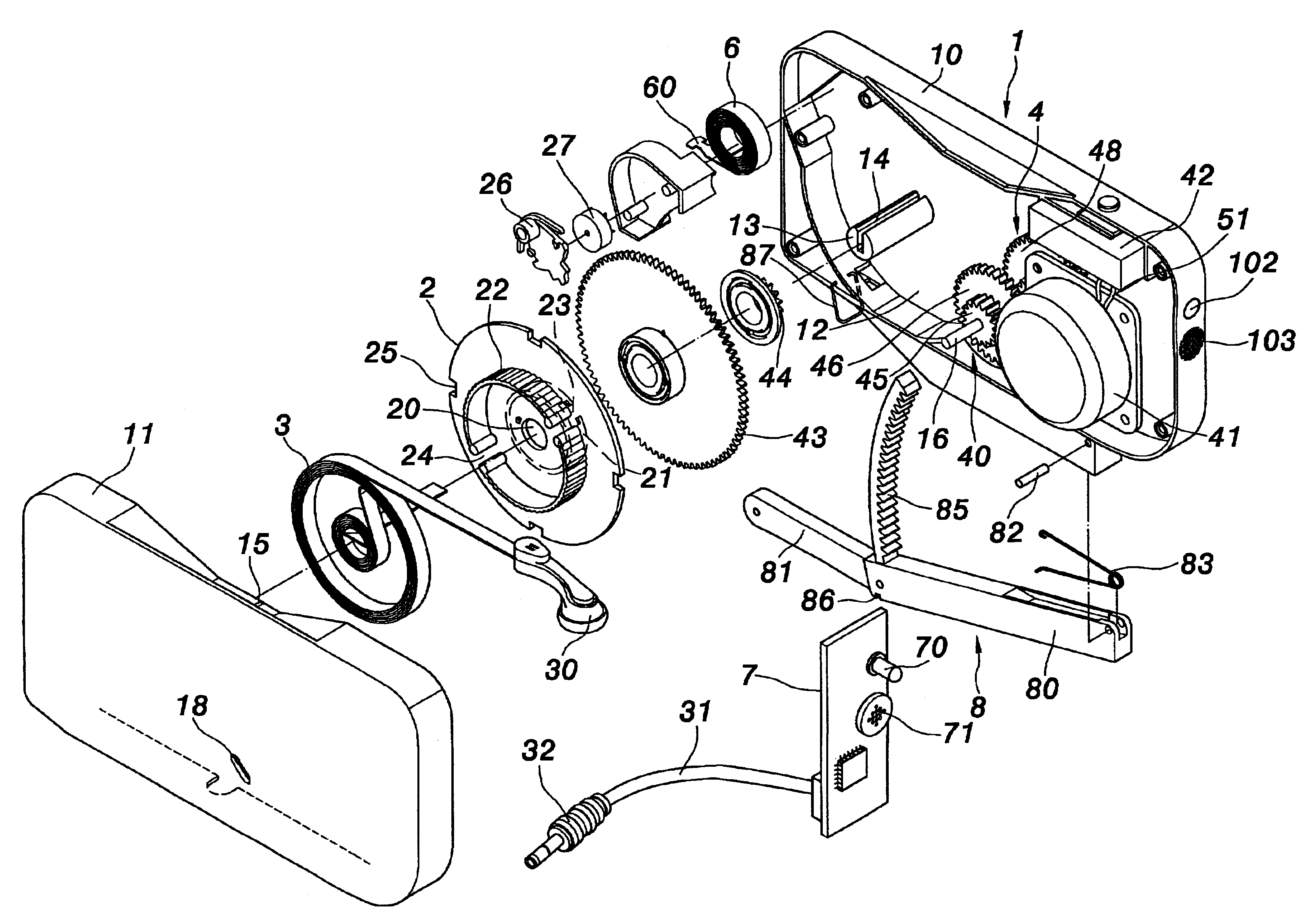
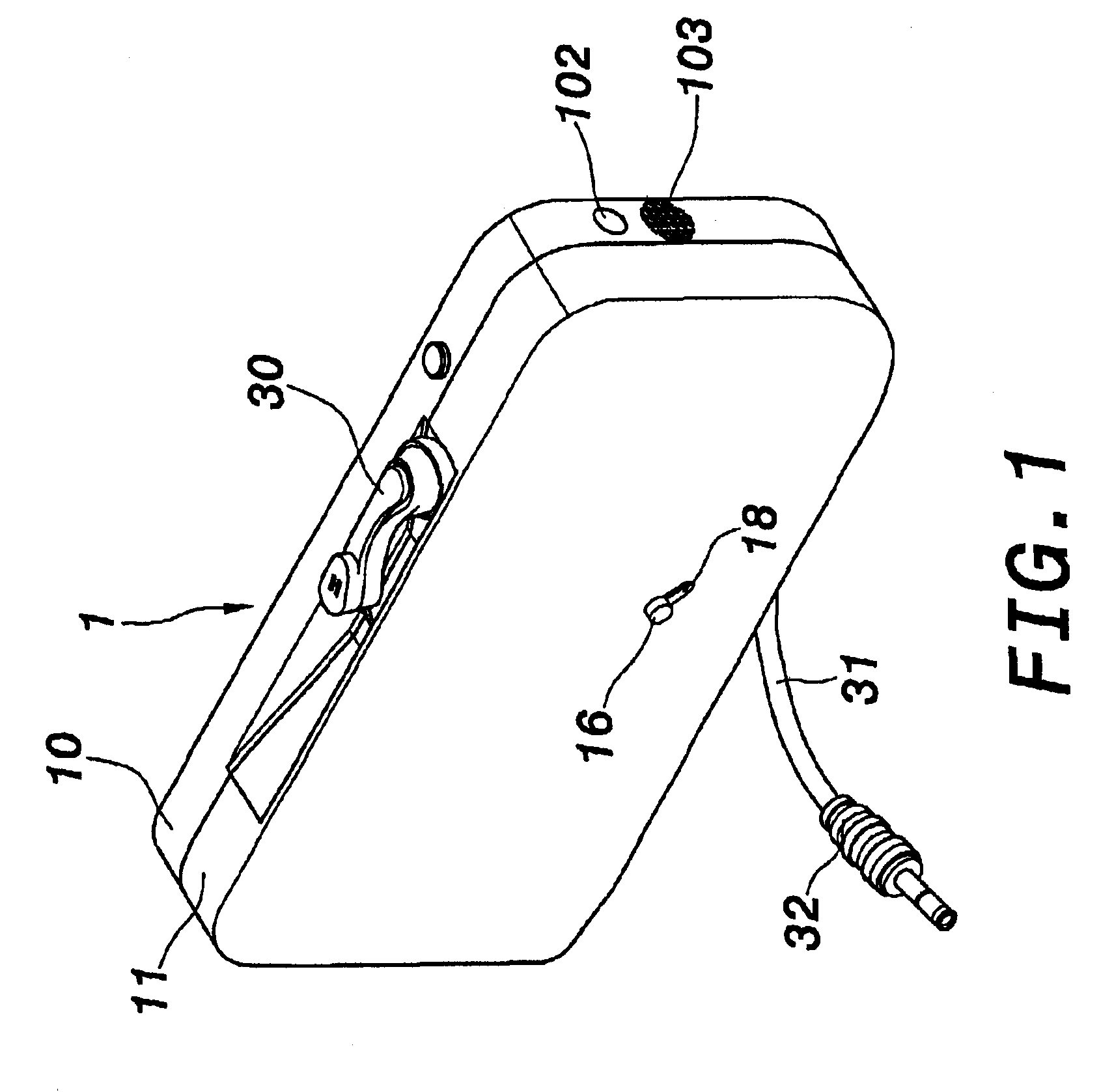
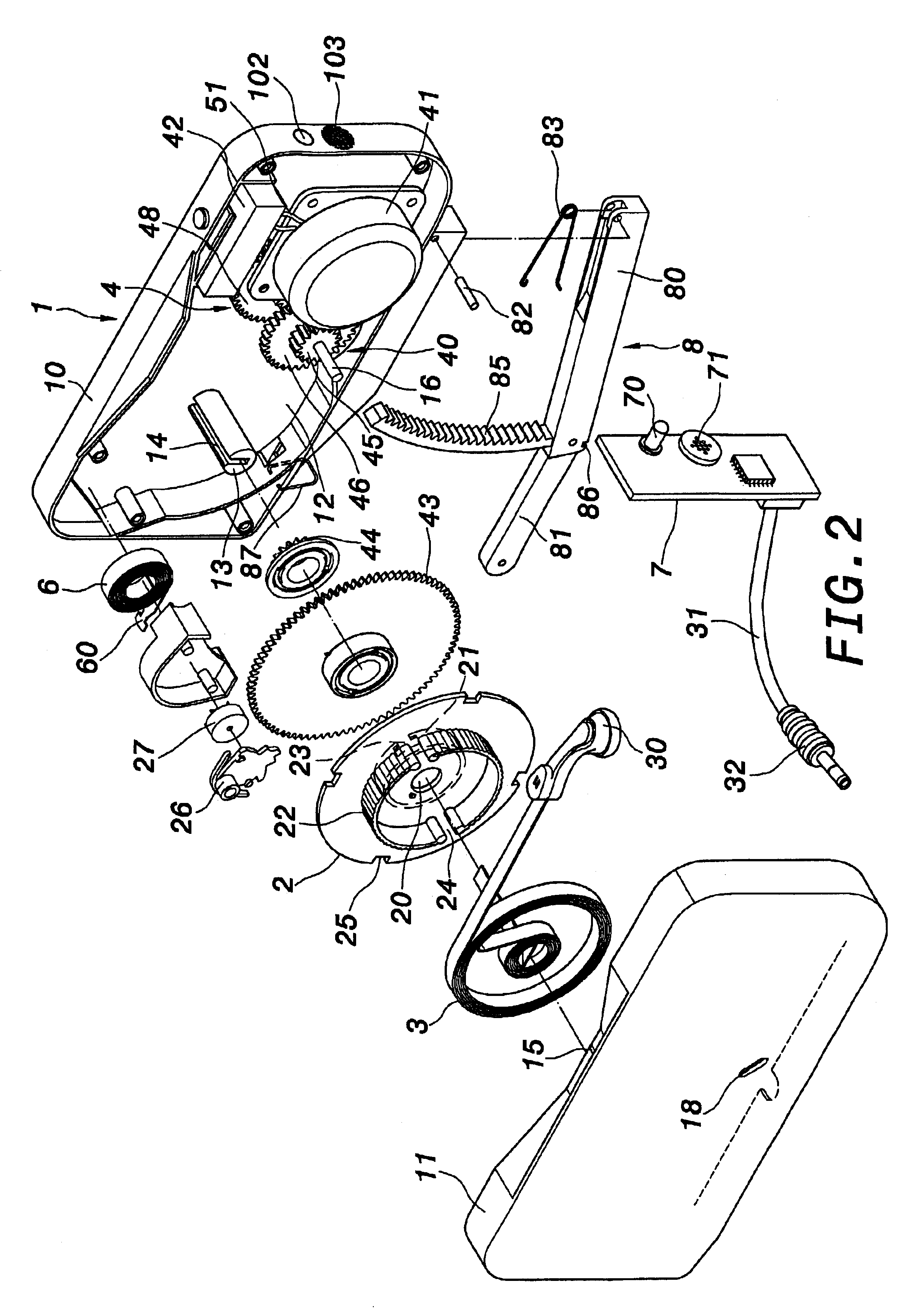
As shown in FIGS. 1 through 5 that illustrate the preferred embodiments of the present invention of a wire rewinding box with a recharge unit, including a casing 1, a windlass 2, a communication wire 3, a recharge unit 4 and a press handle 8, wherein:

The casing 1 consists of a first half casing 10 and a second half casing 11 that are combined as one unit, containing an accommodating chamber 12 inside. The accommodating chamber 12 has a shaft 13. The shaft 13 has a wire channel 14. At one side of the casing 1 is a wire outlet 15. Also inside the accommodating chamber 12 is the windlass 2. The windlass 2 has a shaft hole 20 that is inserted by the shaft 13 to enable rotation. On two side of the windlass are respectively a first winding rim 21 and a second winding rim 22. The first winding rim 21 has a hook groove 23, onto which is engaged a hook end 60 of a coil spring 6 on an outside of the windlass 2, so the coil spring 6 is installed between the casing 1 and the windlass 2, providi...


PUM


Abstract

A wire rewinding box with a recharge unit, including a casing, a windlass, a coil spring, a communication wire, a recharge unit and a press handle. Inside the casing is the formation of an accommodating chamber. The windlass is installed in the accommodating chamber. The coil spring is installed between the casing and the windlass. The communication wire is wound on the windlass. The recharge unit is installed inside the casing, consisting of a gear mechanism, a generator and a battery. The press handle is installed at one side of the casing. The gear mechanism is installed between the windlass, the press handle and the generator.

Description

BACKGROUND OF THE INVENTION(a) Field of the InventionThe invention relates to a wire rewinding box with a recharge unit particularly a wire rewinding box with a recharge unit that has been developed for application on various communication appliances for short-distance cable transmission, providing a length of communication wire that can be pulled out for use, and automatically rewound after the use, to avoid the wire from tangling up, and in the process of pulling the communication wire or pressing a press handle, is capable of generating or recharging power.(b) Description of the Prior ArtCommunication wires are required to connect various communication appliances, such as computer, modem, telephone or facsimile machine. To avoid too long or too many communication wires that may end up tangled up in knots, the inventor had developed a variety of wire rewinding boxes that are applicable to various communication appliances, and had filed applications for patents, such as Taiwan Pate...

Claims


Application Information

Patent Timeline
IPC IPC(8): H02G11/02H02G11/00B65H75/44
CPCB65H75/4449H04M1/15H02G11/02
Inventor LIAO, SHENG HSIN
Owner LIAO SHENG HSIN
Learn More