

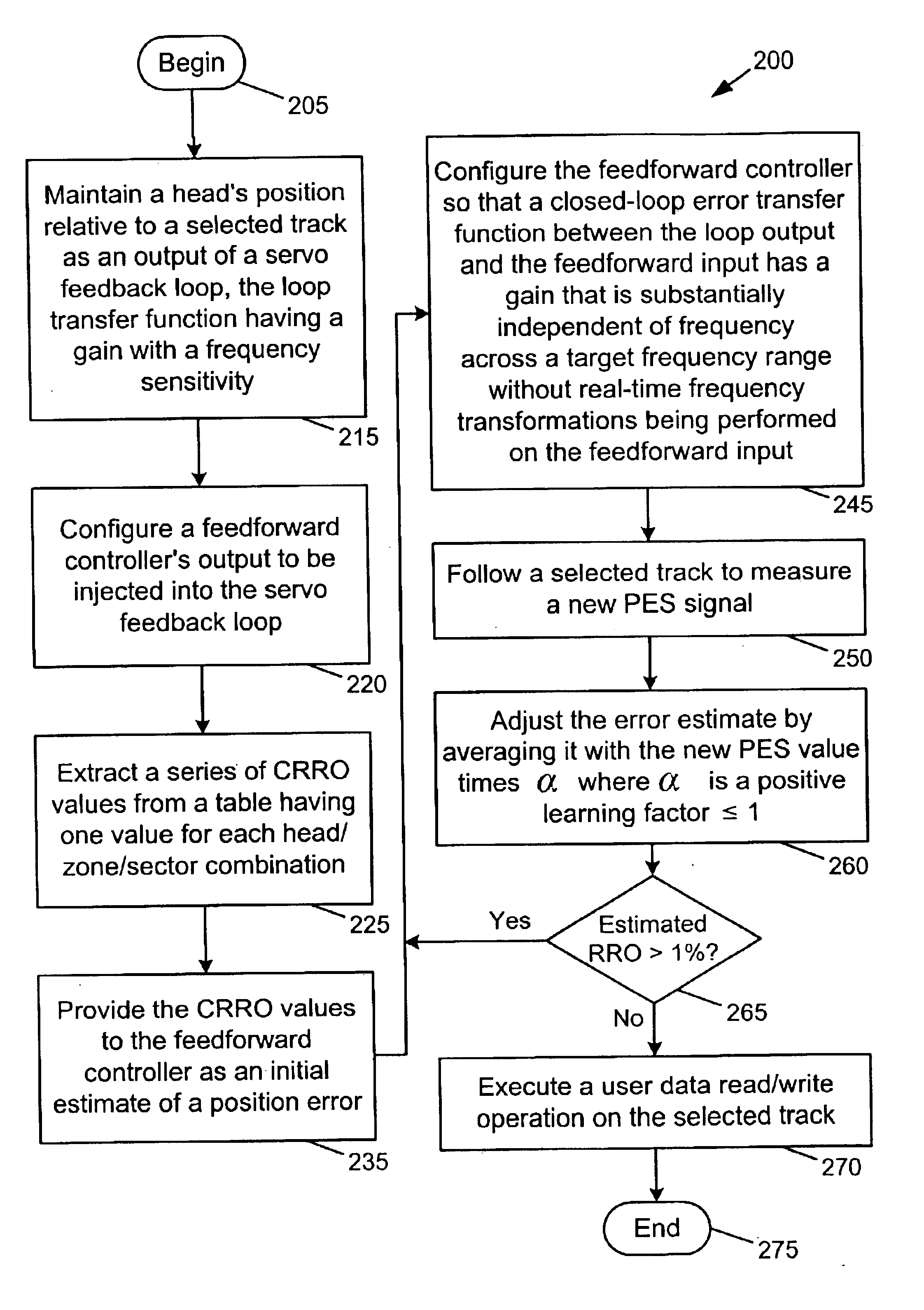
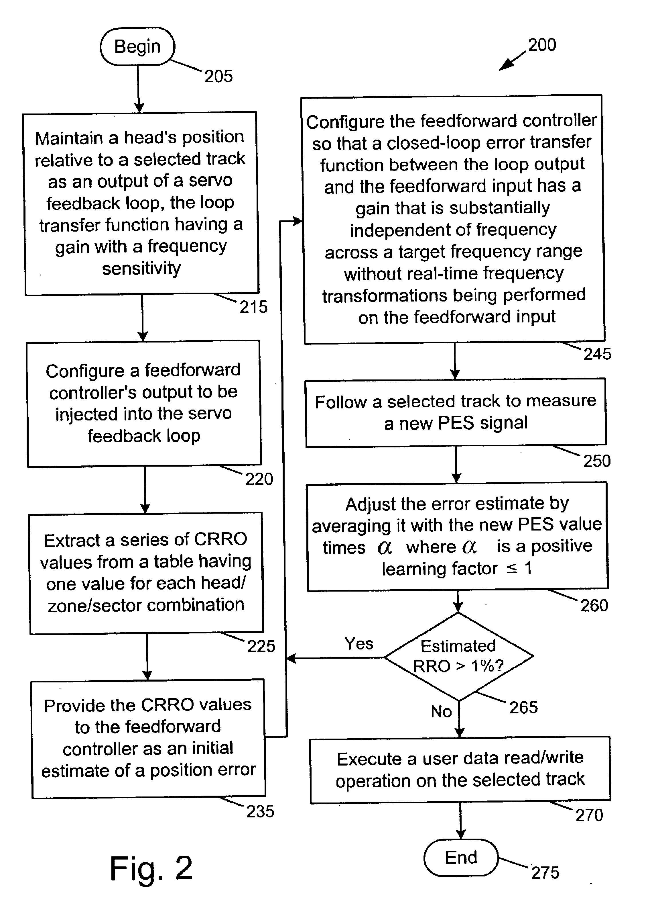
Method and apparatus for feedforward repeatable runout compensation in a selected frequency range
a repeatable runout and frequency range technology, applied in the field of data storage devices, can solve the problems of excessive time-consuming methods, substantial errors in the shape and/or position of tracks, and the implementation of the method may cost too much
- Summary
- Abstract
- Description
- Claims
- Application Information
AI Technical Summary
Benefits of technology
Problems solved by technology
Method used
Image

Examples
Embodiment Construction
Although the examples below show more than enough detail to allow those skilled in the art to practice the present invention, subject matter regarded as the invention is broader than any single example below. The scope of the present invention is distinctly defined, however, in the claims at the end of this document.
Numerous aspects of data storage device technology that are not a part of the present invention (or are well known in the art) are omitted for brevity, avoiding needless distractions from the essence of the present invention. For example, this document does not include specifics of how PES is manipulated in a conventional servo loop to control actuators that position transducer heads. Neither does it include specific methods for receiving, queuing, and executing user commands. Specific techniques for implementing transfer functions specified by formulae or Bode plots in circuitry or software are likewise omitted, typically being a matter of design choice to those of ordi...
PUM
| Property | Measurement | Unit |
|---|---|---|
| frequency | aaaaa | aaaaa |
| frequency | aaaaa | aaaaa |
| harmonic frequencies | aaaaa | aaaaa |
Abstract
Description
Claims
Application Information