Volume control pedal

a volume control and pedal technology, applied in the direction of transducer details, amplification control details, instruments, etc., can solve the problems of increasing costs, exacerbated problems, and high investment requirements, and achieve the effect of preserving the high end frequencies in the audio signal and high impedance outpu

Inactive Publication Date: 2005-02-22
HILTON KEITH L
View PDF5 Cites 10 Cited by
  • Summary
  • Abstract
  • Description
  • Claims
  • Application Information

AI Technical Summary

Benefits of technology

It is a further object of the invention to introduce a pre-amp between an audio instrument's magnetic pickup and the inventive light-beam control circuit in order to present the magnetic pickup with a high impedance output and thereby better preserve the high end frequencies in the audio signal.

Problems solved by technology

Audio product manufacturers find that keeping an on-hand stock in sufficient quantities of a diverse assortment of different potentiometers of premium quality is an expensive investment.
Every year the problem is exacerbated by rising costs, discontinued product lines, and the gradual cheapening of quality.
In audio work, even slight changes in quality produce discernible problems in the final audio output.
However the inventor hereof finds that the logarithmic-taper potentiometers he has experimented were undesirably inconsistent.
Just as problematical, an audio equipment manufacturer can only obtain whichever taper profiles that potentiometer OEM's offer off-the-shelf unless the manufacturer is so large it can afford to order custom potentiometers.
Regardless, the selection of potentiometers is fairly limited to a finite number of different products.
In the professional music world these light beam pedals had a sour reputation.
There were at least three well-known problems with them:—they lost high-end frequency, they would often not go all the way OFF, and they didn't rock very comfortably underfoot.
The failure to go to full OFF appeared to be due to leakage of ambient light onto the photo-resistors.
Although there is no felt drag or friction between a shutter and light beam, the drag that the prior art light beam pedals introduced by way of springs still felt unnatural underfoot.
The spring arrangements of the prior art failed to adequately balance the treadle in the position chosen for the moment by the musician (if he pulled his foot off).
These and other problems have plagued the prior art light beam pedals out of disfavor and virtual disuse, not all of which problems were likely discovered by the studies of the inventor hereof.

Method used


Image

  • Volume control pedal
  • Volume control pedal
  • Volume control pedal

Examples


Embodiment Construction

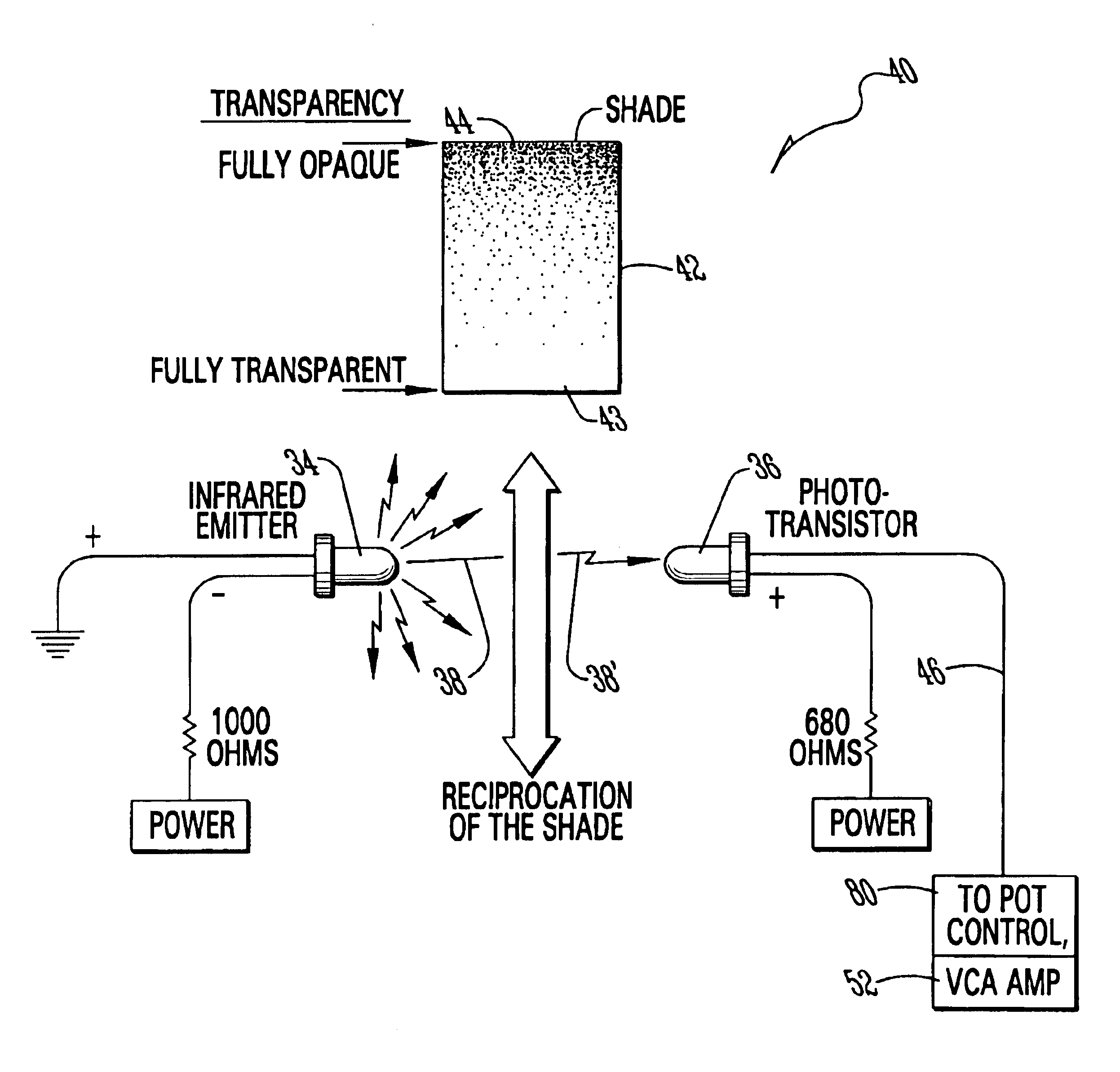
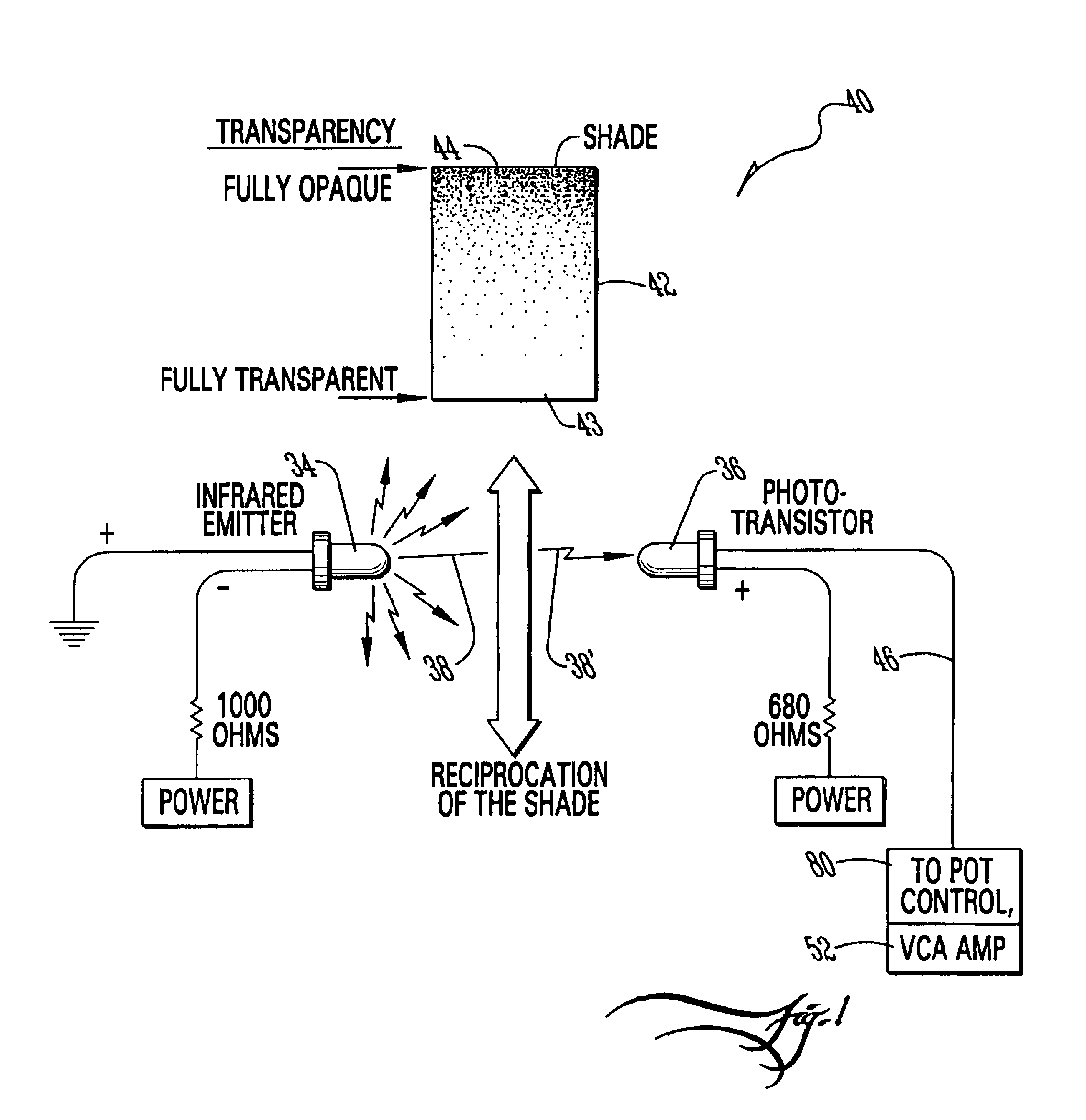
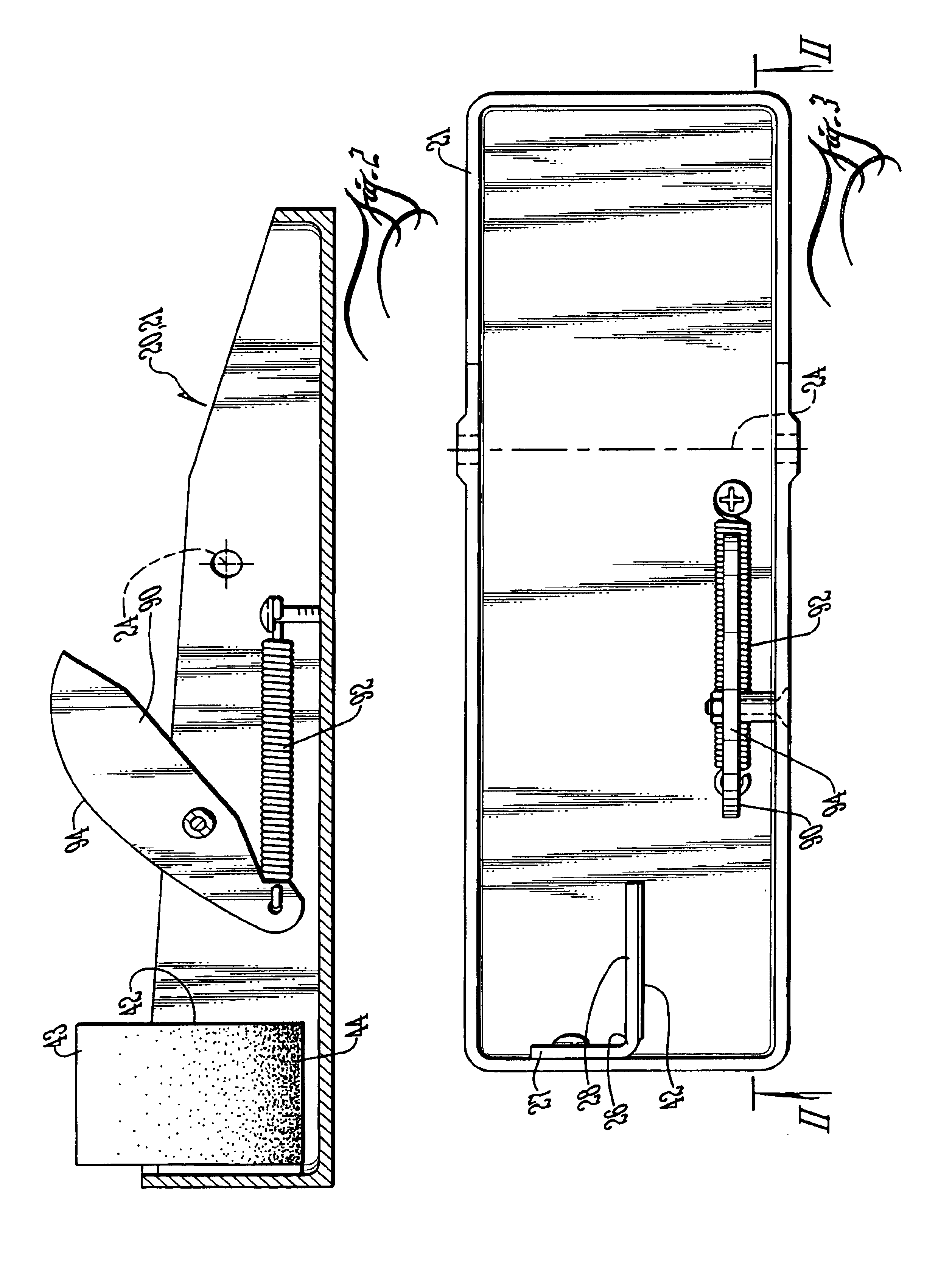
FIG. 1 shows a control signal system 40 in accordance with the invention for a volume control pedal 20 in accordance with the invention. The clam-shell housing 21,22 of the volume control pedal 20 is shown in separate halves 21 and 22 by FIGS. 2 and 4. In FIG. 2, it shows the base half 21 that sets on the floor. FIG. 4 shows the upper or rocking treadle portion 22. The rocking treadle 22 and base 21 connect by a pivot pin (not shown) that extends through the respective pin apertures along the rocking axis 24 of the treadle 22.

The base 21 carries a plastic mounting bracket 26 which in one example version of the invention is produced from transparent acetate. The flange 27 of the bracket 26 is fastened to a wall of the base 21. The stem 28 of the bracket 26 provides a mounting surface for a polyester film or “shade”42 which will be more particularly described below. The treadle 22 carries an inverted U-shaped mounting block 30 that has arms 32 which extend down to lower terminations f...


PUM


Abstract

A volume control pedal has an opposed emitter and receiver which are set up to establish an emission path therebetween. A shade is provided to intersect the emission path. Pedal operation induces relative displacement between the shade and emission that as a result varies the emission reception such that the receiver's output provides a control variable for volume control. The shade has a varying regions of light and dark as rendered by an image of a varying dot density pattern. This allows among other things producing the image by a computer-implemented process, as well as printing it on transparent stock such as optionally on a negative film by a film developing process.

Description

BACKGROUND OF THE INVENTION1. Field of the InventionThe invention relates to a volume control pedal for musicians and more particularly relates to the pedal's circuitry as well as aspects of the mechanical construction in view of such circuitry.2. Prior ArtPedals for volume control are popular with performing musicians, whether vocalists or instrumentalists performing on, by way of non-limiting example, guitars, steel guitars, fiddles and so on. Volume control pedals are popular despite if a sound control engineer is involved. Musicians simply desire independent control of boosting or fading their performance at times when the feeling is there and in order to achieve certain effects.Prior art volume control pedals have characteristically relied on potentiometers such as pulley-spun dial-type potentiometers for voltage control. It is an object of the invention to provide a distinctive alternative to potentiometers, dial- or plunger-type or otherwise, in a volume control pedal.Elimina...

Claims


Application Information

Patent Timeline
Patent Type & Authority Patents(United States)
IPC IPC(8): G10H1/46G10H1/055G10H1/34H03G1/00H03G1/02
CPCG10H1/0553G10H1/348H03G1/02G10H1/46G10H2220/305
Inventor HILTON, KEITH L.
Owner HILTON KEITH L
Why Eureka
Try Eureka