Apparatus and method for measuring the weight of an occupant in a vehicle

a technology for measuring the weight of an occupant and a vehicle seat, which is applied in the direction of instruments, apparatus for force/torque/work measurement, tractors, etc., can solve the problems of not providing an accurate measurement of the weight of the occupant, the sensor the seat and any sensor coupled to the seat is subject to error-inducing loads, so as to prevent inaccurate readings of the occupant.

Inactive Publication Date: 2005-02-22
ROBERT BOSCH CORP
View PDF36 Cites 20 Cited by
  • Summary
  • Abstract
  • Description
  • Claims
  • Application Information

AI Technical Summary

Benefits of technology

Some embodiments of the invention provide an apparatus for measuring a load on a load-bearing platform. For example, specific embodiments of the invention provide an apparatus or bracket for coupling a seat to a floor of a vehicle and measuring the weight of an occupant on the seat. Certain embodiments of the invention are particularly useful at preventing inaccurate readings of an occupant's weight due to extraneous forces placed on the seat and the bracket. In other words, the present invention can isolate the vertical load placed on a seat (which is due primarily to the weight of the occupant) from other extraneous, non-vertical forces placed on the seat by accelerations and decelerations of the vehicle and the like. As will be described in greater detail below, some embodiments use one or more pivots, levers, and sensors to filter out non-vertical loads from vertical loads.

Problems solved by technology

Many of these devices, however, do not provide an accurate measure of the occupant's weight because additional forces other than the occupant's weight are also measured by the sensor.
Specifically, the seat and any sensor coupled to the seat is subject to error-inducing loads caused by forces in the X, Y, and Z directions and moments about the X, Y, and Z directions.
These error-inducing loads (or forces) can be transferred to the sensor and cause the sensor to generate incorrect information.

Method used


Image

  • Apparatus and method for measuring the weight of an occupant in a vehicle
  • Apparatus and method for measuring the weight of an occupant in a vehicle
  • Apparatus and method for measuring the weight of an occupant in a vehicle

Examples


first embodiment

Several embodiments of the present invention will be described below. Some features of each embodiment are similar and are therefore given similar reference numbers. For example, a feature labeled as element “9” in one embodiment, may be labeled as element “109,”“209,” etc. in other embodiments. Although some features may share a common number, it does not mean that the features are identical. Rather, it indicates that these features are similarly situated, share structural similarities, or perform similar functions. The features that are common to one or more embodiments will generally only be described once. Thus, it will be described in the first embodiment in which it appears. The descriptions of common elements will generally not be repeated in subsequent embodiments. Thus, reference to previous embodiments may be required in some instances to fully understand certain embodiments.

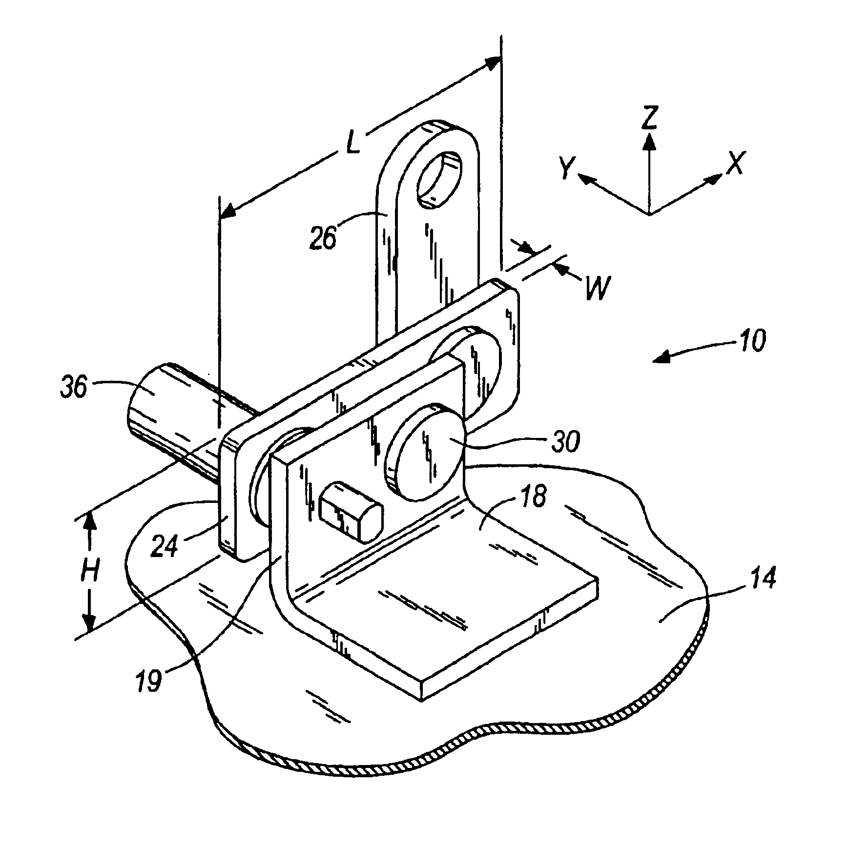
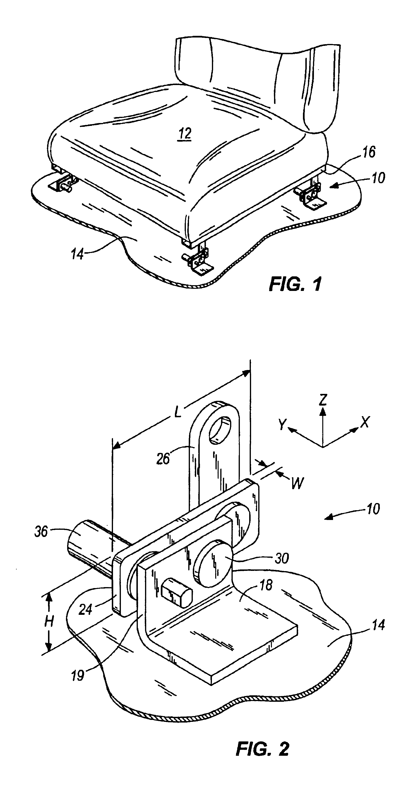
FIG. 1 illustrates a plurality of brackets 10 positioned below a seat 12 to support and connect the...

second embodiment

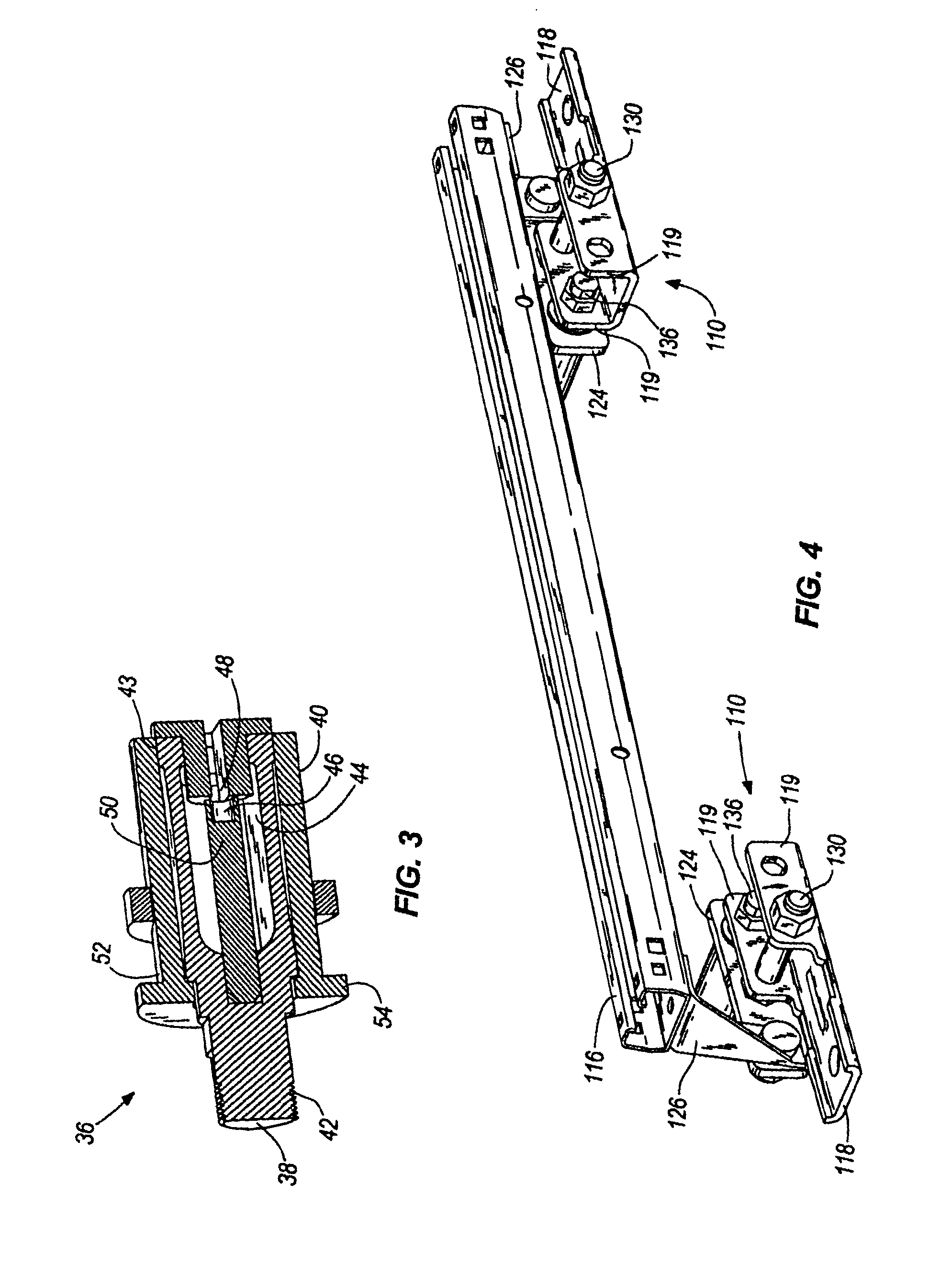
the invention is illustrated in FIGS. 4-7. As illustrated in these figures, this embodiment has many similar features to the first embodiment. Therefore, only the main differences between the two embodiments will be discussed in detail.

Like the previous embodiment, the bracket 110 of this embodiment has a support 118, a lever 124 coupled to the support 118 via a pivot 130 and a sensor 136 coupled to the support 118 and the lever 124. The support 118 of this embodiment is slightly different than the previous embodiment. While the previous embodiment had only one portion or flange 19 that extended upward from the floor of the vehicle to support the pivot 30, the present embodiment has two flanges 119 that extend up from the floor of the vehicle to support the pivot 130. As illustrated, the pivot 130 extends from the first flange 119 to the second flange 119 and then through the lever 124. This arrangement can provide greater stability for the pivot 130 to help limit the degrees of fre...

third embodiment

the invention is illustrated in FIGS. 8A and 8B. This embodiment operates on similar principles as the previous embodiments. Therefore, only the main differences between the third embodiment and the first and second embodiments will be discussed in detail.

Like the previous embodiments, the bracket 210 of the third embodiment has a support 218, a lever 224 coupled to the support 218 via a pivot 230, and a sensor 236 coupled to the support 218 and the lever 224. Furthermore, the support 218 of this embodiment has two flanges 219 for supporting the pivot 230, like the second embodiment. However, unlike that embodiment, the lever 224 is located between the two flanges 219 rather than on one side of both flanges.

Additionally, the lever 224 is split into two portions: a first portion 227 that is bifurcated or forked and a second portion adjacent the first portion 228. As best illustrated in FIG. 8B, the pivot 230 extends through the bifurcated portion 228. This can provide greater stabili...


PUM


Abstract

An apparatus and method for supporting a load-bearing platform (e.g., a seat) and measuring the weight of a load (e.g., an occupant) on the platform. The apparatus can include a base or support, a lever coupled to the support, and a sensor. The lever can be pivotally coupled to the support to allow pivotal movement of the lever with respect to the support in response to weight applied to the platform. The sensor can detect the force transmitted by the lever to determine the weight of the load on the platform. Furthermore, the lever can isolate the vertical load on the platform due to the weight of the load from other extraneous, non-vertical forces on the platform.

Description

FIELD OF THE INVENTIONThe present invention relates to an apparatus and method for measuring loads. Particularly, the invention relates to an apparatus and method for measuring a load on a load-bearing platform. More particularly, the invention relates to an apparatus and method for measuring the weight of an occupant sitting on a vehicle seat.BACKGROUNDAutomobiles are equipped with seat belts and airbags to provide safety for passengers. In recent years, there is a trend for controlling the operation of such safety devices according to the body weight of a passenger. For example, the amount of gas to be introduced into the airbag, an airbag inflating speed, or a pre-tension of the seat belt may be adjusted according to the weight of a passenger. To optimally use these safety devices, the weight of the seat's occupant must be measured.Several devices have been designed to measure the weight of the occupant while seated. Most of these devices use some form of sensor to measure forces...

Claims


Application Information

Patent Timeline
Patent Type & Authority Patents(United States)
IPC IPC(8): G01G19/414G01G19/40
CPCG01G19/4142
Inventor THAKUR, RAJEEVVANFLEET, CHADGOLSHTEYN, ALEKSANDR
Owner ROBERT BOSCH CORP
Why Eureka
Try Eureka