
Baby diaper changing station

a diaper changing station and diaper technology, applied in the field of diaper changing stations, can solve the problems of affecting the overall decor, affecting the aesthetics, and affecting so as to improve the overall integrity, improve the aesthetics, and improve the overall integrity of the diaper changing station

Inactive Publication Date: 2005-03-01
FOUND WORLDWIDE
View PDF88 Cites 11 Cited by
  • Summary
  • Abstract
  • Description
  • Claims
  • Application Information

AI Technical Summary

Benefits of technology

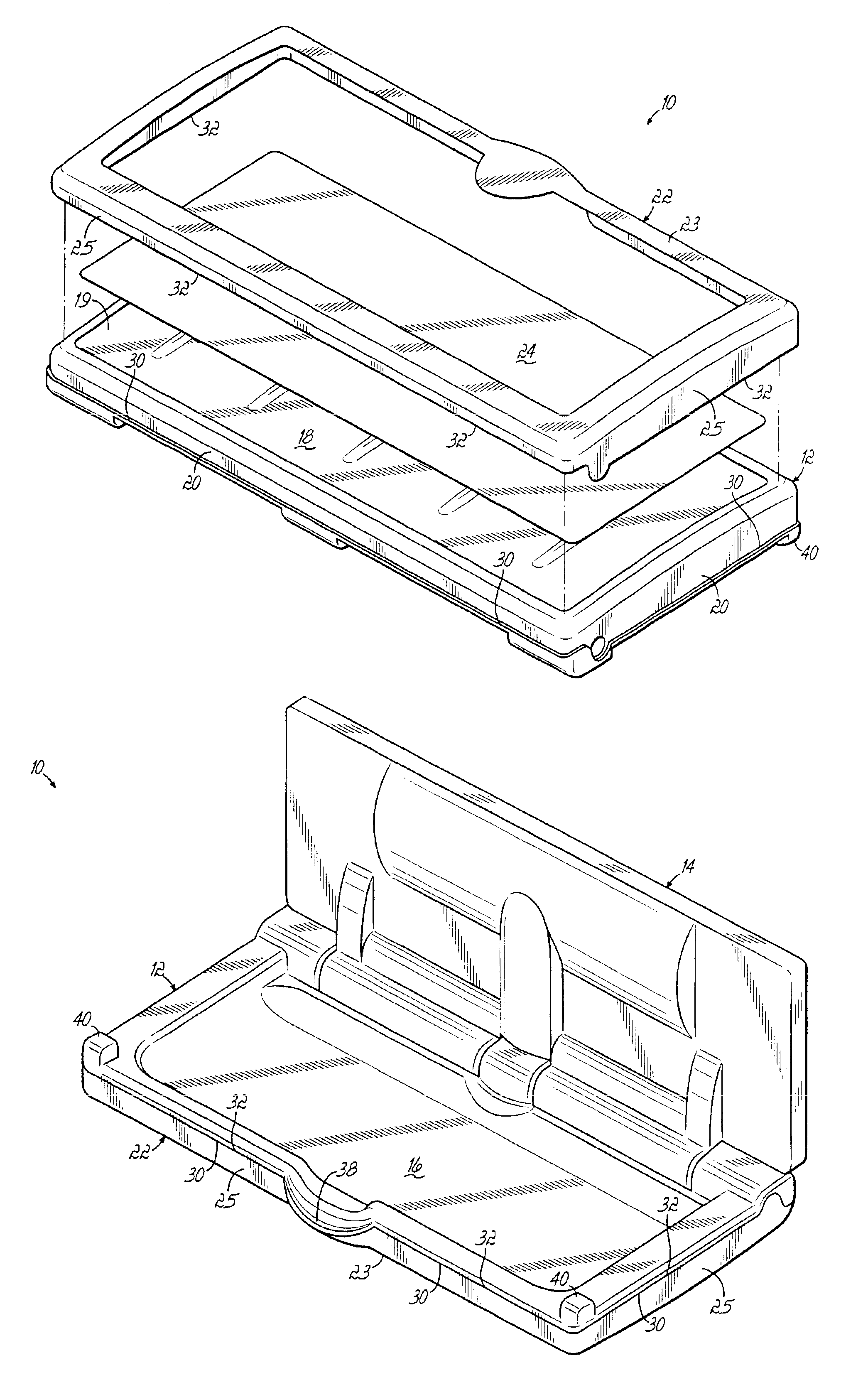
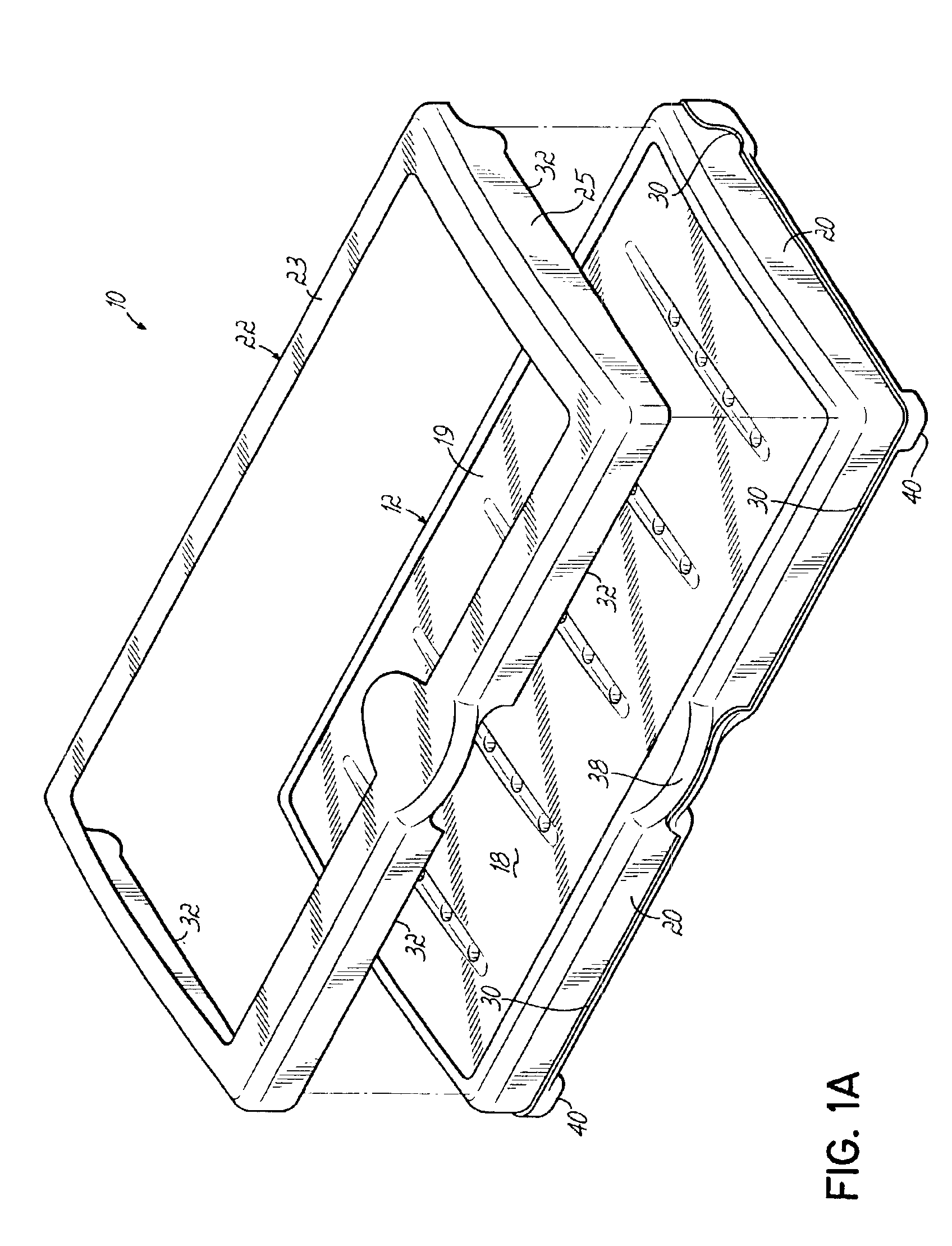
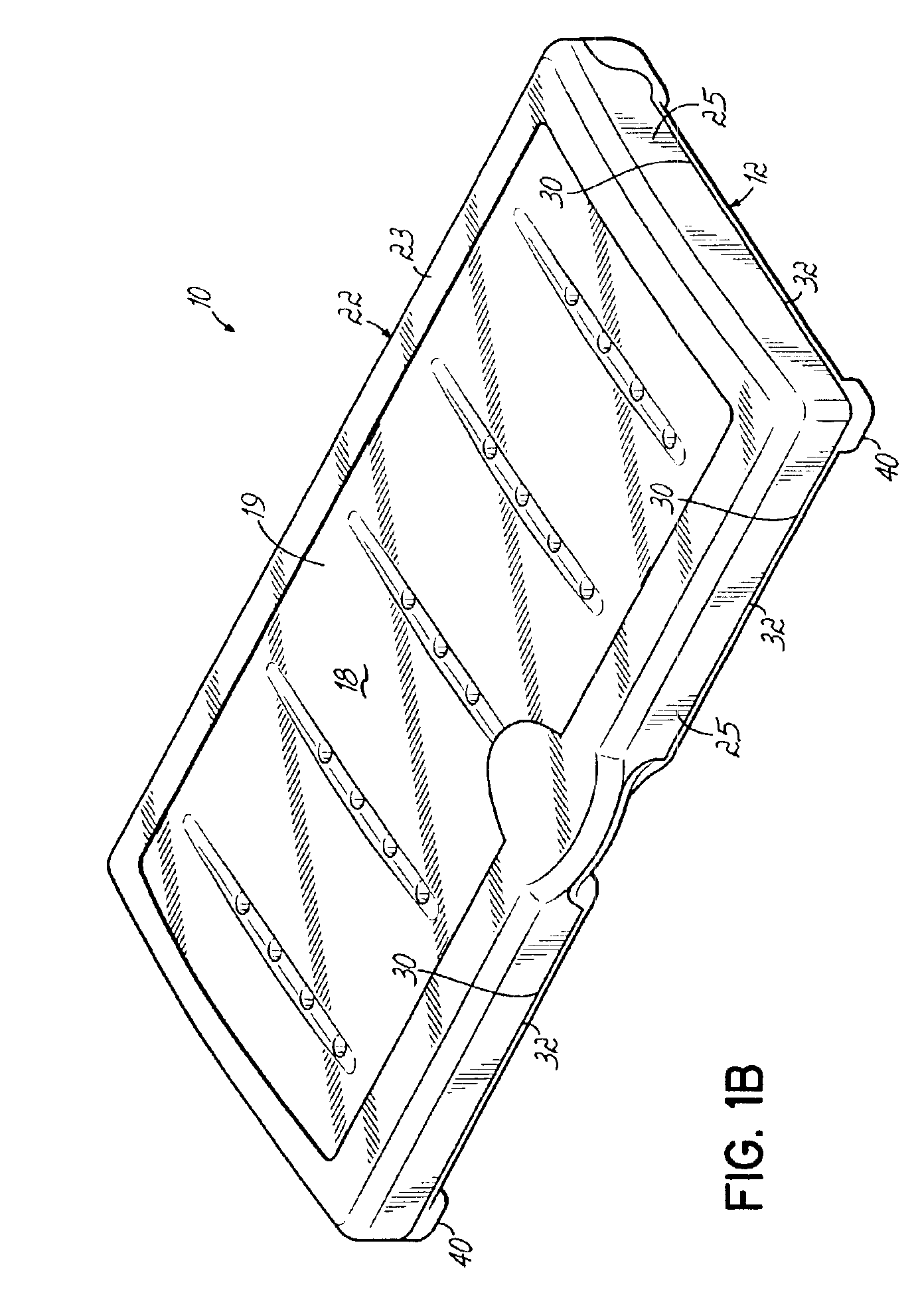
In accordance with one aspect of the invention, a panel is configured to overlie and cover at least a portion of the bottom surface. The panel is generally exposed when the support platform is in the closed position. A frame structure is configured to engage the bottom surface and side surfaces of the support platform for securement thereto. The frame structure is configured to secure the panel with the support platform when the frame structure is coupled to the support platform. A lip is formed around at least one of the side surfaces of the platform, and preferably around all the exposed side surfaces. An edge of the frame structure abuts the lip when the frame structure engages the support platform. In that way, a seamless appearance and construction, which improves the aesthetics, cleanability, and overall integrity of the diaper changing station, is presented.
In accordance with another aspect of the present invention, a support platform might be utilized generally without a lip. The frame structure is configured to engage the bottom and side surfaces of the support platform for securing the panel. A molding element engages an edge of the frame structure, and is tapered at an edge thereof to meet a surface of the frame structure or a surface of the support platform. In one embodiment, the opposing edges of the molding element are tapered for tapering down to and engaging both the surface of the frame structure and the surface of the support platform to present a seamless appearance.
In accordance with yet another aspect of the present invention, the base includes a backer plate, which is configured for mounting to a wall, and specifically to studs in a wall. The backer plate has a cleat and is oriented to form generally a horizontal ledge with the cleat. Another backer plate is coupled with the base of the diaper changing station and has a cleat positioned thereon to engage and oppose the cleat of the wall backer plate. The engaging cleats of the opposing backer plates provide support of the base on the wall when the diaper changing station is mounted to the wall. The backer plates ensure that the station may be mounted to wall studs despite its location and without the need for specialized blocking. The backer plates further enhance the support provided by other fastening structures utilized to affix the diaper changing station to the wall.

Problems solved by technology

One particular drawback to existing baby changing apparatuses is the fact that most such apparatuses are fabricated of a single neutral color which, more often than not, does not match the color schemes of tile and vanity surfaces utilized within the restroom facility.
Existing single color baby changing apparatuses detract from the overall decor because their large, neutral exposed surfaces clash with the colors within the restroom area.
Furthermore, since the off-color baby changing apparatuses are mounted to a wall, they are particularly noticeable, further detracting from the decor.
When the baby-supporting platform is in an up and closed position, a large amount of exposed surface area against the wall of the restroom presents a distinct clash with other restroom apparatuses and surfaces.
Existing baby changing stations are also particularly subject to defacement since they are located on the walls of public restroom facilities.
As noted, when the baby changing station is in the closed position, it presents a large outer surface area which somewhat invites vandalism.
Vandals generally mark the outer surface with graffiti and scrape and abrade the exposed surfaces.
The soft plastic of the molded station is particularly susceptible to such abrasion and other damage.
As may be appreciated, such vandalism discourages use of the changing station by protective parents and further degrades the overall appearance of cleanliness within the restroom facility sending a message of neglect to users of the facility.
The graffiti and vandalism is often permanent on the exposed surfaces of the changing station and requires the costly remedy of replacing an entire changing station.
Furthermore, if sufficient vandalism occurs, it may only be necessary to replace the panel rather than the whole changer.
However, while such panels improve upon the overall look, damage resistance and practicality of changing stations, they present other issues.
Not only may such edges detract from the fit and finish, but they may also collect dirt and other foreign material.
As may be expected this may degrade the appearance and perceived cleanliness of the changer.
Such extra measures increase the overall cost of constructing or retrofitting the facility, but may be required for ideal securement and for spreading the load of the changing station over the support structures.
In addition to the extra costs and time, such blocked areas are generally pre-selected and, thus, do not allow for mounting flexibility based upon field conditions.
If the changing station is to be moved, then another area has to be blocked, additional drawings have to be made, etc., further driving up costs.

Method used


Image

  • Baby diaper changing station
  • Baby diaper changing station
  • Baby diaper changing station

Examples


Embodiment Construction

FIG. 1A illustrates a portion of a baby diaper changing station 10 in accordance with one aspect of the present invention. Specifically, station 10 shows a support platform 12, which is appropriately formed to be hingeably fixable, or otherwise secured, at an edge thereof with respect to a wall surface, and specifically with respect to a base 14, as illustrated in FIG. 3. The base 14 is mounted to a wall surface. The support platform moves between an open position for use (see FIG. 3) and a closed position up against a wall surface, as is typical in the art. The support platform, in one example, might be molded with an appropriate plastic, such as high density polyethylene (HDPE). The support platform generally includes a top surface 16, bottom surface 18, and side surfaces 20. The top surface, when the support platform is in the open position as illustrated in FIG. 3, is oriented generally horizontally and is configured for supporting a child, such as an infant or a toddler, above ...


PUM


Abstract

A diaper changing station includes a support platform configured for supporting a child and having a bottom surface and side surfaces. The support platform is hingedly fixable at an edge with respect to a wall to move between an open position and a closed position against the wall. A panel is configured to overlie and cover at least a portion of the bottom surface and to be generally exposed when the support platform is in the closed position. A frame structure is configured to engage the bottom surface and side surfaces of the support platform for securement thereto. The frame structure secures the panel with the support platform. A lip is formed around the side surfaces of the platform. An edge of the frame structure abuts the lip when the frame structure engages the support platform to present a seamless appearance. In another aspect, the changing station includes a backer plate coupled to the base and having a cleat. Another backer plate is mounted to a wall and has a cleat. The station backer plate is positioned to engage the cleat of the wall backer plate for supporting the base when the diaper changing station is mounted to a wall.

Description

FIELD OF THE INVENTIONThe present invention relates to an apparatus for changing the diapers of an infant or toddler.BACKGROUND OF THE INVENTIONApparatuses for changing the diapers of a baby or for “changing a baby” and other small children not yet toilet trained, have become widely used, such as in public restrooms, to assist a parent or other child supervisor when changing a baby's diapers. Such baby diaper changing apparatuses, often times referred to as simply baby changing stations, have taken various forms as evidenced by patents in the field, and generally take the form of a base which is mounted vertically onto a surface of a wall and a support platform or surface which is hingedly mounted to the base to hinge down from the base and lie generally horizontal to support a baby. While available baby changing apparatuses may operate sufficiently for the primary purpose of offering a generally horizontal surface on which to rest a baby during a diaper change, it is still desirabl...

Claims


Application Information

Patent Timeline
IPC IPC(8): A47D3/00
CPCA47D5/003A47D5/006Y10S5/947
Inventor HELMSDERFER, JOHN A.
Owner FOUND WORLDWIDE
Learn More