Fluidic oscillator

Active Publication Date: 2005-03-01
NATIONAL TSING HUA UNIVERSITY
View PDF7 Cites 33 Cited by
  • Summary
  • Abstract
  • Description
  • Claims
  • Application Information

AI Technical Summary

Benefits of technology

A main object of the present invention is to provide a fluidic oscillator for a flowmeter, wherein a regulating shoulder is formed on each of the attachment walls wi...

Problems solved by technology

However, if the velocity of the flow is over the measuring range, the flow...

Method used


Image

  • Fluidic oscillator
  • Fluidic oscillator
  • Fluidic oscillator

Examples


Embodiment Construction

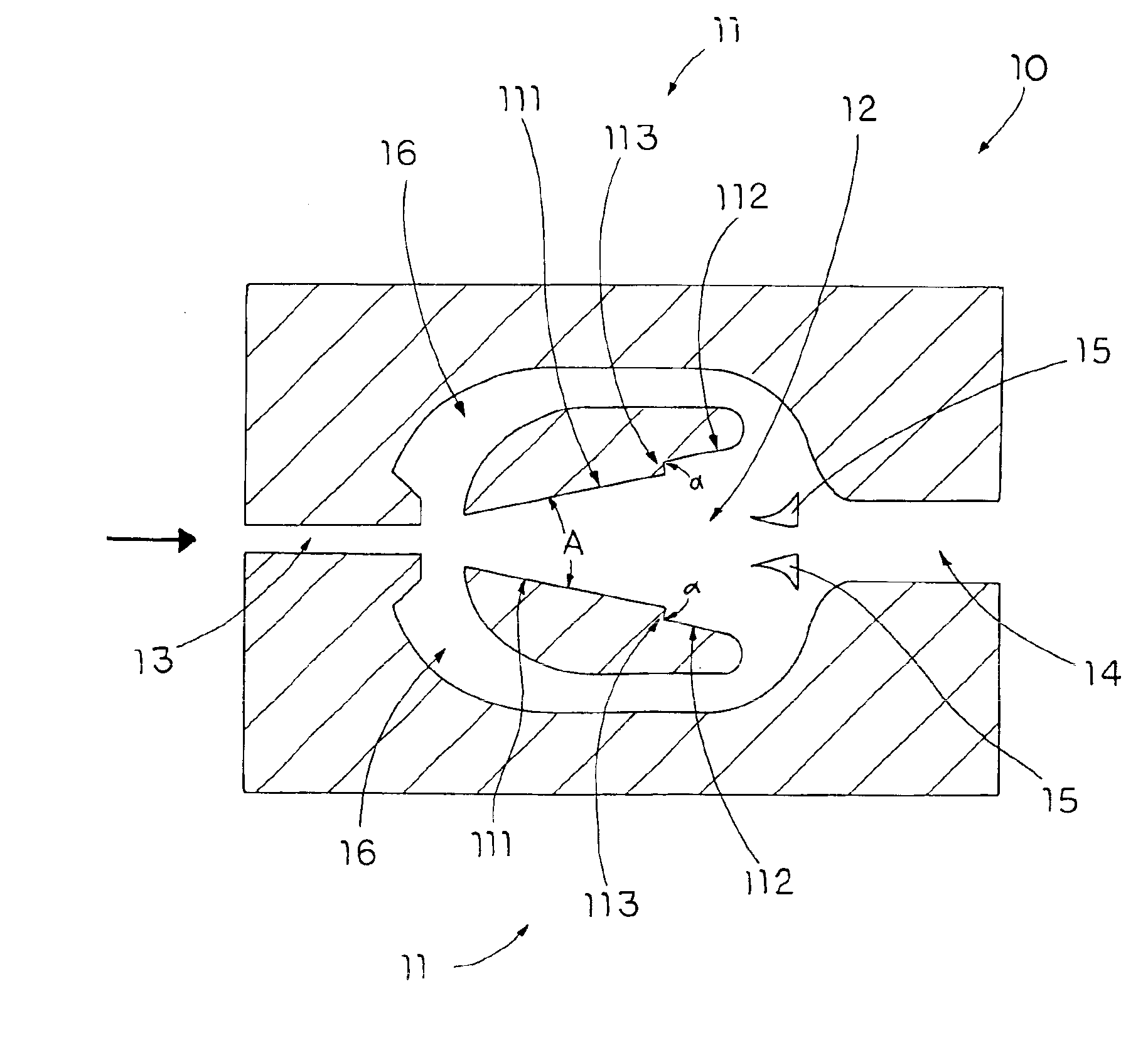
Refer ring to FIGS. 4 and 5, a fluidic oscillator according to a preferred embodiment of the present invention is illustrates, wherein the fluidic oscillator comprises an oscillator body 10 having two attachment walls 11 defining an oscillating chamber 12 therebetween, an inlet duct 13 communicatively extended from the oscillating chamber 12 for guiding a flow of fluid entering into the oscillating chamber 12, an outlet duct 14 communicatively extend ed from the oscillating chamber 12 to align with the inlet duct 13 for guiding the flow of fluid exiting from the oscillating chamber 12, a flow splitter 15 provided at the outlet duct 14 to communicate with the oscillating chamber 12, and two feedback channels 16 communicating with the oscillating chamber 12.

Each of the feedback channels 16 is extended from the outlet duct 14 at the flow splitter 15 to the inlet duct 13 for splitting the flow of fluid to flow from the oscillating chamber 12 back to the inlet duct 13. To amplify the fee...


PUM


Abstract

A fluidic oscillator includes an oscillator body having two attachment walls defining an oscillating chamber therebetween, an inlet duct communicatively extended from the oscillating chamber for guiding a flow of fluid entering into the oscillating chamber, an outlet duct communicatively extended from the oscillating chamber for guiding the flow of fluid exiting from the oscillating chamber, a flow splitter provided at the outlet duct to communicate with the oscillating chamber, and two feedback channels communicating with the oscillating chamber. Each of the attachment walls has an upstream portion and a downstream portion integrally extended therefrom as a step shouldering manner to form a modulating shoulder for modulating an oscillation of the flow within the oscillation chamber so as to stabilize the flow of the fluid to pass through the oscillator body.

Description

BACKGROUND OF THE PRESENT INVENTION1. Field of InventionThe present invention relates to hydrodynamic measuring device, and more particularly to a fluidic oscillator for a flowmeter, wherein when a flow of fluid passes through an oscillation chamber of the fluidic oscillator, the flow rate of the fluid is linearly proportional to the frequency of the fluidic oscillation for minimizing the turbulent of the fluid within the fluidic oscillator so as to precisely measure the flow of fluid.2. Description of Related ArtsA conventional fluidic oscillator is generally employed in a flowmeter for measuring a flow of fluid. The conventional fluidic oscillator generally comprises an oscillator body having two attachment walls 1A defining an oscillating chamber 2A therebetween, an inlet 3A extended from the oscillating chamber 2A, an outlet 4A extended from the oscillating chamber 2A, a splitter 5A provided at the outlet duct 4A, and two feedback channels 6A communicating with the oscillating c...

Claims


Application Information

Patent Timeline
CPCG01F1/3227Y10T137/224
Inventor YANG, JING-TANGLIN, WEI-CHIHTSAI, KUEN-JYHHUANG, KER-JER
Owner NATIONAL TSING HUA UNIVERSITY
Why Eureka
Try Eureka