Inhaler

a technology of inhaler and inhaler, which is applied in the field of inhalers, can solve problems such as unsuitable full dose delivery

Inactive Publication Date: 2005-03-01
ASTRAZENECA AB
View PDF16 Cites 62 Cited by
  • Summary
  • Abstract
  • Description
  • Claims
  • Application Information

AI Technical Summary

Benefits of technology

By use of a damping element to delay release of the compressed canister, it is possible to control the period for which the canister is held compressed. Typically, such a period will be between 100 and 5000 ms. Use of damping has been found to be advantageous over a mechanical arrangement introducing a time delay. A mechanical arrangement must be manufactured with tight tolerances to properly control the delay and tend to decrease in precision over time. In contrast a damping element is easily controllable and does not lose timing accuracy.
In this case, the locking element may be arranged to lock the loading element in its second position for locking the canister in its compressed state after release of the triggering mechanism. Such a structure prevents the locking element from interfering with the operation of the actuation mechanism to deliver a dose.
Desirably, the pre-loading mechanism further comprises a canister engagement lever biassed by the resilient loading element when loaded to compress the canister, the triggering mechanism engaging the cannister engagement lever to hold and release the stored actuation force, wherein the release member is resiliently biassed by a resilient biassing element acting between the canister engagement member and the release member. As the canister engagement member itself compresses the canister, this prevents movement of the release member before compression of the canister and hence reduces the chance of a premature re-set of the canister.

Problems solved by technology

However, if the compression of the canister is released to allow re-set of the valve stem too early, then a full dose is not properly delivered.

Method used


Image

  • Inhaler
  • Inhaler
  • Inhaler

Examples


Embodiment Construction

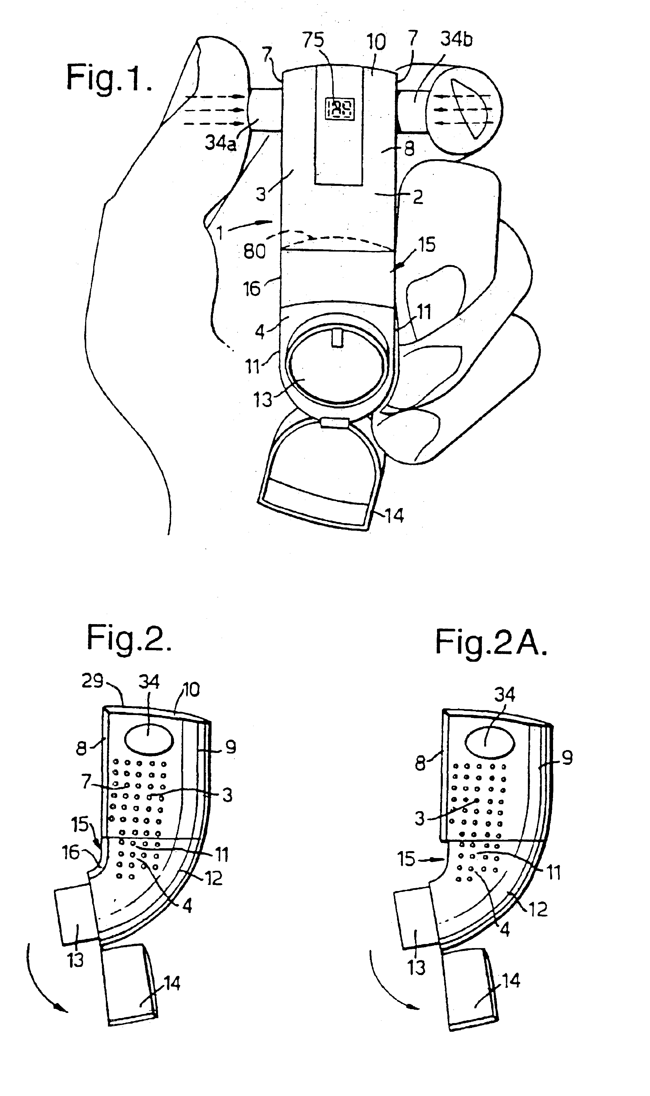
An inhaler 1 which embodies the present invention is illustrated in FIGS. 1 and 2, respectively showing the front view of the inhaler 1 held in a user's hand and a side view of the inhaler.

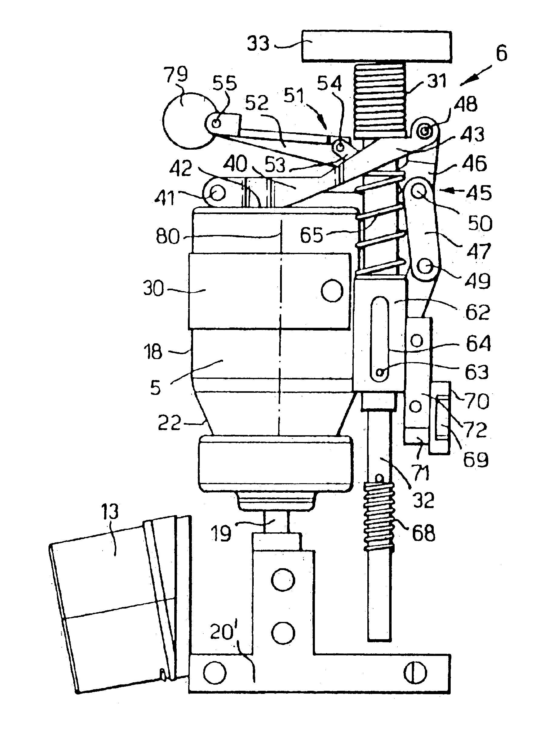
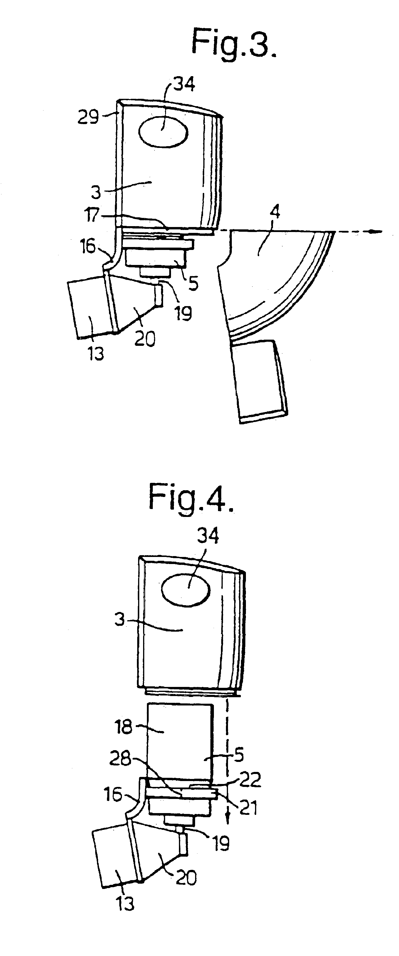
The inhaler has a housing 2 comprising an upper housing portion 3 and a lower housing portion 4 which are coupled together. The upper and lower housing portions 3 and 4 have outer walls which are hollow to define a space accommodating a canister 5 of medicament and an actuation mechanism 6 operatable to actuate the canister 5 to deliver a dose of medicament.

The upper housing portion 3 has opposed side walls 7 joined by a flat front wall 8, a curved rear wall 9 and a top wall 10. The lower housing portion 3 has opposed side walls 11 fitting flush with the side walls 7 of the upper housing portion 3 and a curved rear wall 12 fitting flush with the rear wall 9 of the upper housing portion 3. The rear walls 12 and 9 together form a curved surface comfortably received in the palm of the user's hand as ...


PUM


Abstract

An inhaler for delivering medicament by inhalation, comprising a housing for holding a canister of medicament having a body and a valve stem compressible together to actuate the canister to deliver a dose of medicament from the valve stem, an actuation mechanism for compressing the canister, a cannister re-set mechanism comprising a locking element for locking the canister in a compressed state and a release member resiliently biassed by the actuation mechanism on compression of the canister to release the locking mechanism to allow reset of the canister. By provision of the locking element for locking the canister in a compressed state, it is possible to ensure re-set does not occur immediately. The release member subsequently releases the locking mechanism to allow re-set of the canister after a proper dose has been delivered. The cannister reset mechanism further comprises a damping element for damping movement of the release member to delay the action of the resilient biassing to release the locking element a predetermined period of time after actuation of the canister.

Description

BACKGROUND OF THE INVENTIONInhalers are commonly used for delivery of a wide range of medicaments. The inhaler holds a cannister of medicament which is actuated by compression to deliver a dose of medicament through a mouthpiece. The inhaler may be provided with an actuation mechanism for compressing the canister. This may be a breath-actuated mechanism which is arranged to actuate the canister in response to inhalation at the mouthpiece. Typically, a breath-actuated inhaler includes a pre-loading mechanism for loading a resilient loading element with an actuation force for compression of the canister and a triggering mechanism arranged to hold the resilient loading element against compression of the canister and to release the resilient loading element on inhalation.Known canisters comprise a body having a protruding valve stem and an internal metering chamber which receives a dose of medicament stored in the body. Compression of the valve stem into the body causes the medicament i...

Claims


Application Information

Patent Timeline
Patent Type & Authority Patents(United States)
IPC IPC(8): A61M15/00
CPCA61M15/009A61M15/0091A61M15/0068A61M2205/6045A61M2205/582A61M15/0096
Inventor CHRISTRUP, S.O SLASHED.RENGEERT-JENSEN, ANDERSJ.O SLASHED.RGENSEN, MIKAELRASMUSSEN, J.O SLASHED.RGENSCHMIDT, HUGO DINES
Owner ASTRAZENECA AB
Why Eureka
Try Eureka