Material melting device of metal injection molding machine

Inactive Publication Date: 2005-03-01
WU CHI YIN +2
View PDF3 Cites 15 Cited by
  • Summary
  • Abstract
  • Description
  • Claims
  • Application Information

AI Technical Summary

Benefits of technology

The various objects and advantages of the present invention will be more readily understood

Problems solved by technology

However, metals are heavy and dense than plastics.
Moreover, the grains of the metal after melting are not so uniform as plastic grains.
Thereby, conventionally, a feeding screw rod with screw threads at the middle section is used to feed material, but this will induce bubbles to be accumulated in the metal material.
As a result, the surface of the product is not uniform

Method used


Image

  • Material melting device of metal injection molding machine
  • Material melting device of metal injection molding machine
  • Material melting device of metal injection molding machine

Examples


Embodiment Construction

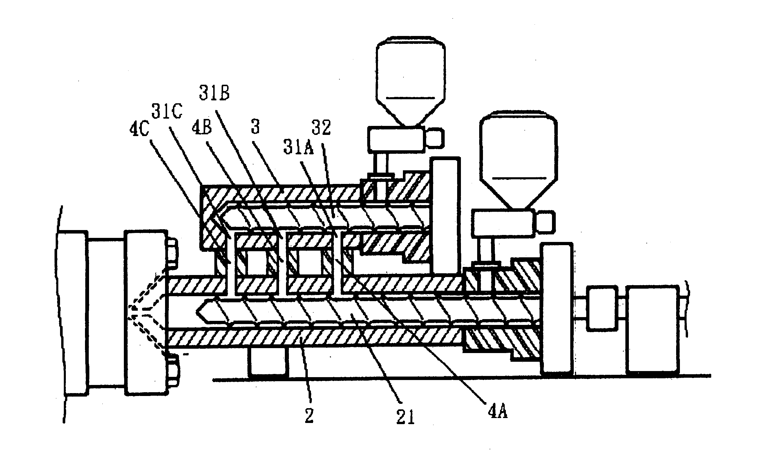
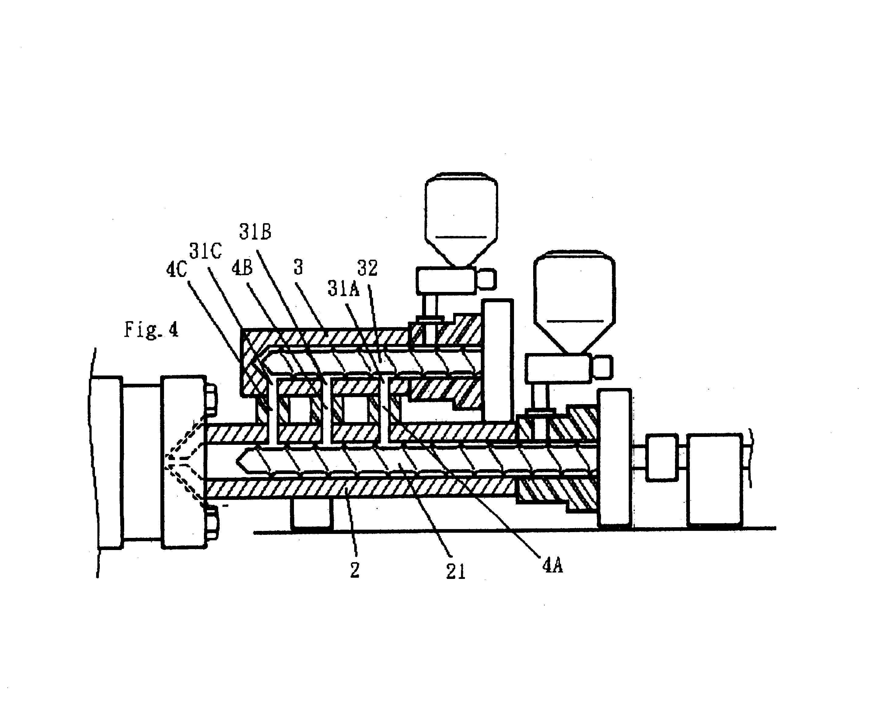
Referring to FIGS. 4 and 4A, in the present invention, a lateral side of a main feeding cylinder 2 of a metal injection molding machine is arranged with a plurality of preheating feed cylinders 3 which are parallel arranged. A side of each preheating feed cylinder 3 is formed with a plurality of material outlets 31A, 31B and 31C. The material outlets 31A, 31B and 31C are communicated to the main feeding cylinder 2 through the guide tubes 4A, 4B and 4C. Thereby, the inner side of the preheating feed cylinder 3 can be, pre-heated so as to get preheated grains 5A, 5B and 5C by adjusting rotating speed of the preheating screw rods 32 in the preheating feed cylinders 3.

The material 5 drops into the main feeding cylinder 2 from the material outlets 31A, 31B and 31C. The material 5 dropped from the material outlet 31A forms the preheated grains 5A which are hard, the material 5 dropped from the material outlet 31B forms the preheated grains 5B, the material 5 dropped from the material outl...


PUM


Abstract

A material melting device of metal injection molding machine comprises a main feeding cylinder; a plurality of preheating feed cylinders parallel arranged at a lateral side of a main feeding cylinder of a metal injection molding machine; a plurality of material outlets formed at a side of each preheating feed cylinder. The material outlets are communicated to the main feeding cylinder through the guide tubes. Thereby, an inner side of the preheating feed cylinder is pre-heated so as to get preheated grains by adjusting the preheating screw rods in the preheating feed cylinder. Moreover, the preheating feed cylinders can be replaced by feeding funnels and the guide tubes are replaced by heating pipes.

Description

FIELD OF THE INVENTIONThe present invention relates to metal injection molding machines, and particularly to a material melting device of a metal injection molding machine which causes that the injecting material has a solid structure so that the surface of the product is smooth.BACKGROUND OF THE INVENTIONInjecting machines are mainly used with shaping molds for forming products. Materials are heated, extruded and then fed into a mold. Conventionally plastic material is used due to a low melting point, small grain sizes and preferred uniformity. Moreover, in the process of storage and injection, the material has no bubble therein.Currently, many products, for example, computer casings, use metals as material (for example, aluminum) for replacing plastic material. However, metals are heavy and dense than plastics. Moreover, the grains of the metal after melting are not so uniform as plastic grains. Thereby, conventionally, a feeding screw rod with screw threads at the middle section ...

Claims


Application Information

Patent Timeline
IPC IPC(8): B22D17/20B22D17/08B22D17/10B22D17/30
CPCB22D17/10B22D17/30B22D17/2061Y10S164/90
Inventor WU, CHI YINWANG, HOUHSN, CHIRN SHUN
Owner WU CHI YIN
Why Eureka
Try Eureka