Loader

a loader and path technology, applied in mechanical machines/dredgers, soil shifting machines/dredgers, constructions, etc., can solve the problems of affecting both load and equipment, and achieve the effect of reducing the moment load

Inactive Publication Date: 2005-03-01
PONSSE
View PDF12 Cites 8 Cited by
  • Summary
  • Abstract
  • Description
  • Claims
  • Application Information

AI Technical Summary

Benefits of technology

Although the joint mechanism according to the invention can be applied in connection with both a wide-angle loader and a simple pivoted loader, a particularly advantageous embodiment is the path loader wherein the maneuvering cylinder is located inside the frame of the main boom, as the synchronization can be implemented very easily, to give the end of the hinged boom an essentially straight path in the working area. According to a second embodiment, sliding guides are used to make the telescopic component of the main boom linear. According to a third embodiment, the link rod with its pivots is arranged to carry lateral forces, to reduce the moment load on the telescopic component.

Problems solved by technology

Such a path is quite difficult to achieve by manual operation, which generally results in a path that bounces up and down, which is detrimental to both the load and the equipment.

Method used


Image

  • Loader
  • Loader
  • Loader

Examples


Embodiment Construction

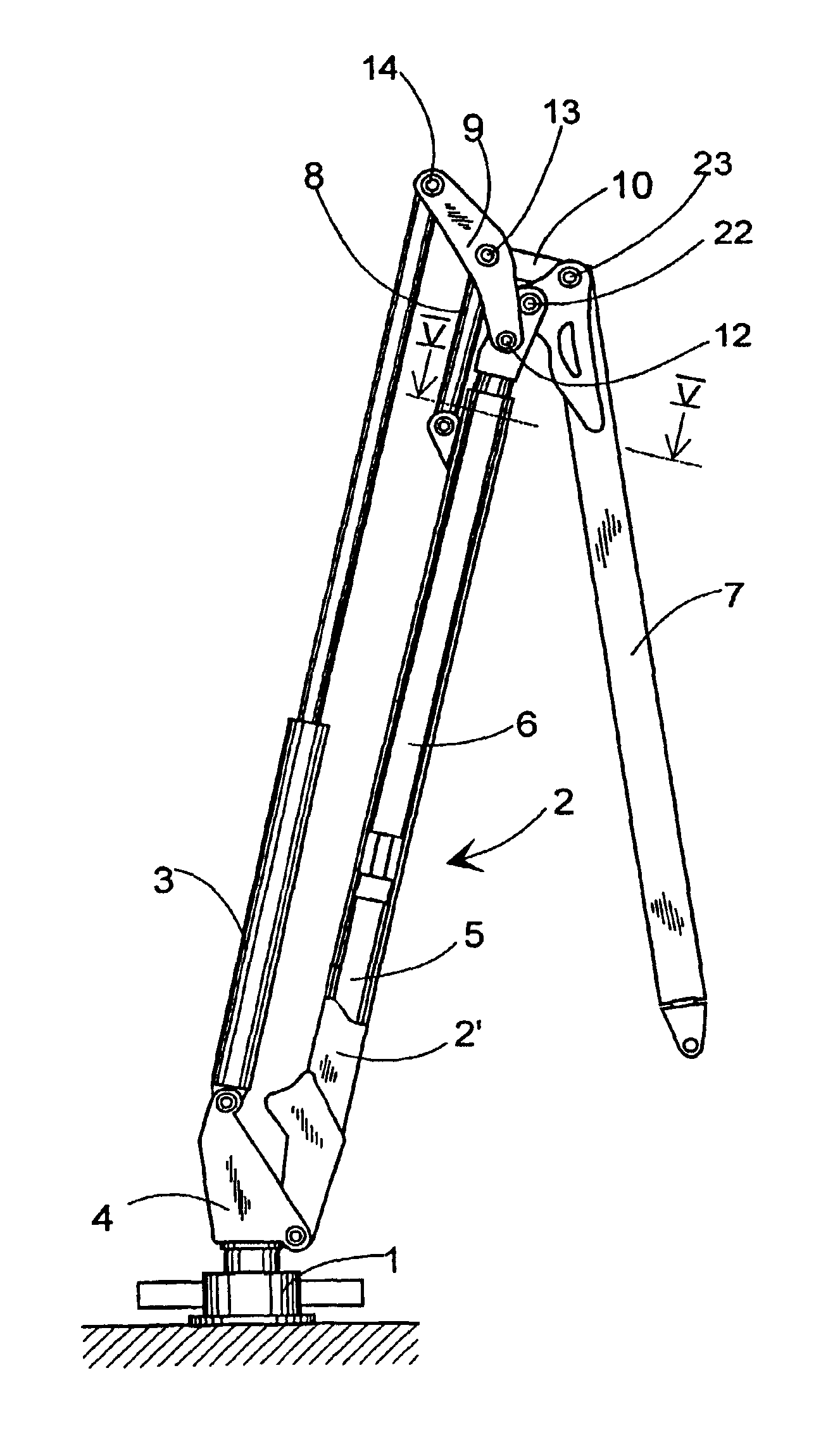
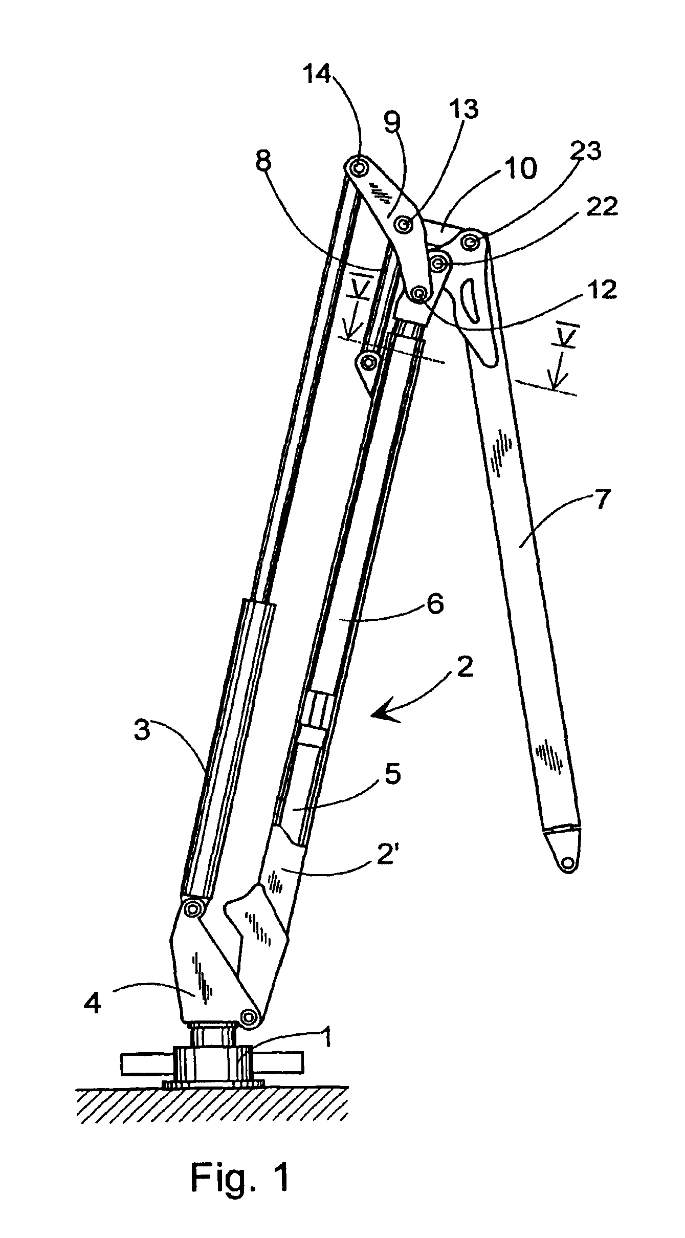
FIG. 1 shows the loader according to the invention, which includes a base 1 equipped with a turning device, by means of which the loader is attached to its carrier machine. The loader's booms, comprising a main boom 2 and a hinged boom 7 are arranged on the base 1. Two cylinders are arranged to operate the booms, i.e. a lifting cylinder 3 and a manoeuvring cylinder 5. The main boom 2 is telescopic, comprising a frame 2′ pivoted on the base 1 and a telescopic component 6 arranged to move linearly in relation to the main boom 2. There are sliding guides, to be described later, between the frame 2′ and the telescopic component 6. The manoeuvring cylinder 5 of the hinged boom 7 is located inside the frame 2′ of the main boom 2 and is arranged to operate the telescopic component 6 of the main boom 2 in relation to the frame 2′ of the main boom. Manoeuvring cylinder 5 is preferably located in the bottom end of the main boom 2. The lifting cylinder 3 is located on the opposite side of the ...


PUM


Abstract

A loader includes a base equipped with a turning device, for attaching the loader to a carrier machine, a telescopic main boom including a frame pivoted on the base, and a telescopic component arranged to move linearly in relation to it and pivoted on the base, a hinged boom pivoted on the main boom, a lifting cylinder pivoted at its first end to the base and at its second end directly or indirectly to the main boom to operate it, an arm directly or indirectly attached to the hinged boom, pivoted to the main boom, a maneuvering cylinder disposed about the main boom between the frame and the telescopic component, the telescopic component is pivoted to the arm operating the hinged boom by the first pivot, the loader includes a link rod pivoted at one end to the frame of the main boom and at the other end to the second pivot of the said arm, which is at a distance from the said first pivot.

Description

TECHNICAL FIELDThe present invention relates to a path loader for a timber handling device, which loader includesa base equipped with a turning device, for attaching the loader to a carrier machine,a main boom pivoted on the base,a hinged boom pivoted on the main boom,a lifting cylinder pivoted at its first end to the base and at its second end directly or indirectly to the main boom to operate it,an arm directly or indirectly attached to the hinged boom, to operate it,a manoeuvring cylinder attached at its first end to the main boom and at its second end to the said arm by means of the first pivot.BACKGROUND OF THE INVENTIONPath loaders of this kind are used especially in timber harvesters. The loader carries various timber handling devices, such as a harvester component, a timber felling head, or a timber grab. The characteristics of such a loader allow it to be used to successfully perform desired operations in timber harvesting and tree felling. The predominant methods are fores...

Claims


Application Information

Patent Timeline
Patent Type & Authority Patents(United States)
IPC IPC(8): E02F3/28E02F3/30B66C23/687
CPCE02F3/306
Inventor SEPPALA, TEIJO
Owner PONSSE
Why Eureka
Try Eureka