X-ray CT apparatus

a technology of x-ray computer and ct apparatus, which is applied in the direction of tomography, material analysis using wave/particle radiation, instruments, etc., can solve the problems of short life of main bearing unit 102, so as to prevent occurrence of deterioration of reconstructed image quality, prolong the life of bearing unit, and reduce the moment load

Inactive Publication Date: 2009-11-24
TOSHIBA MEDICAL SYST CORP
View PDF3 Cites 0 Cited by
  • Summary
  • Abstract
  • Description
  • Claims
  • Application Information

AI Technical Summary

Benefits of technology

[0012]The present invention addresses the abovementioned problems and defects of the conventional X-ray CT apparatus. The present invention provides a new multi-tube type X-ray apparatus that can contain distortions of a rotation due to high speed rotation in order to decrease the moment load added to the bearing units and prolong the life of bearing units. Further, the present invention provides a new multi-tube type X-ray apparatus that can avoid the divergences of X-ray paths between X-ray sources and X-ray detectors in order to prevent occurrence of deteriorations of quality of reconstructed images. Furthermore, the present invention provides a new multi-tube type X-ray apparatus capable of providing early access to rotation units for maintenance in a short time so as to reduce the down time the system.

Problems solved by technology

Consequently, it becomes impossible to support such multiple rotation units in the same sized rotation frame as that of a conventional single tube type X-ray CT apparatus.
This generates a problem that the life of main bearing units 102 becomes short compared with that of the single tube type X-ray CT apparatus.
Such deformation causes divergences of the X-ray paths so that quality of reconstructed images deteriorates.
Since the access operability for the maintenance becomes complicated, the down time of the system also increases, which is also a problem of the conventional multi-tube type X-ray CT apparatus.

Method used


Image

  • X-ray CT apparatus
  • X-ray CT apparatus
  • X-ray CT apparatus

Examples


Embodiment Construction

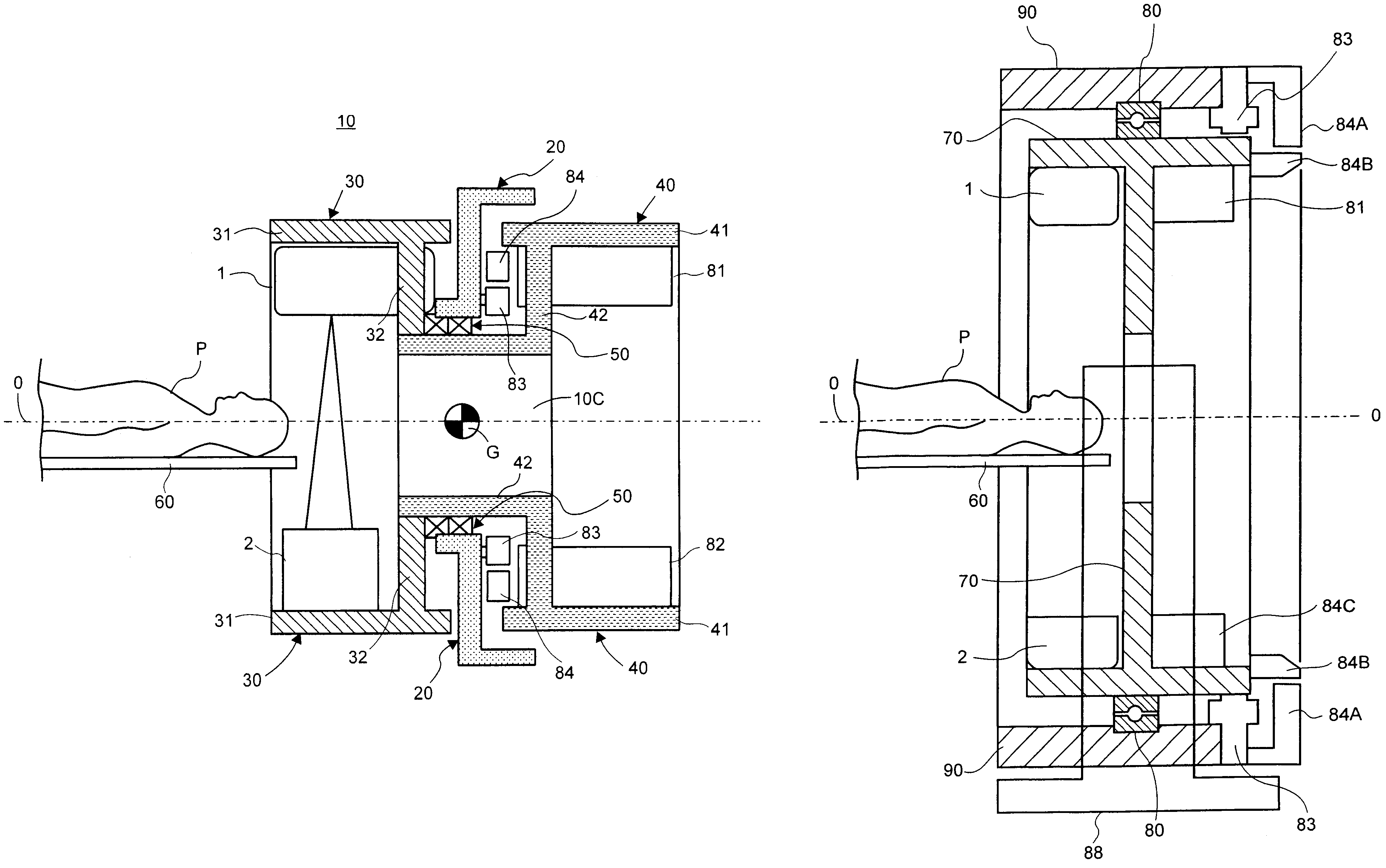
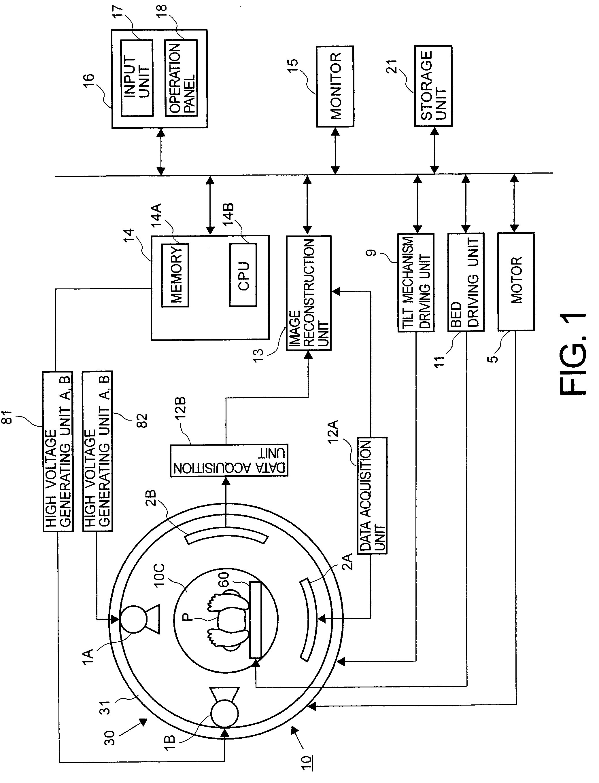
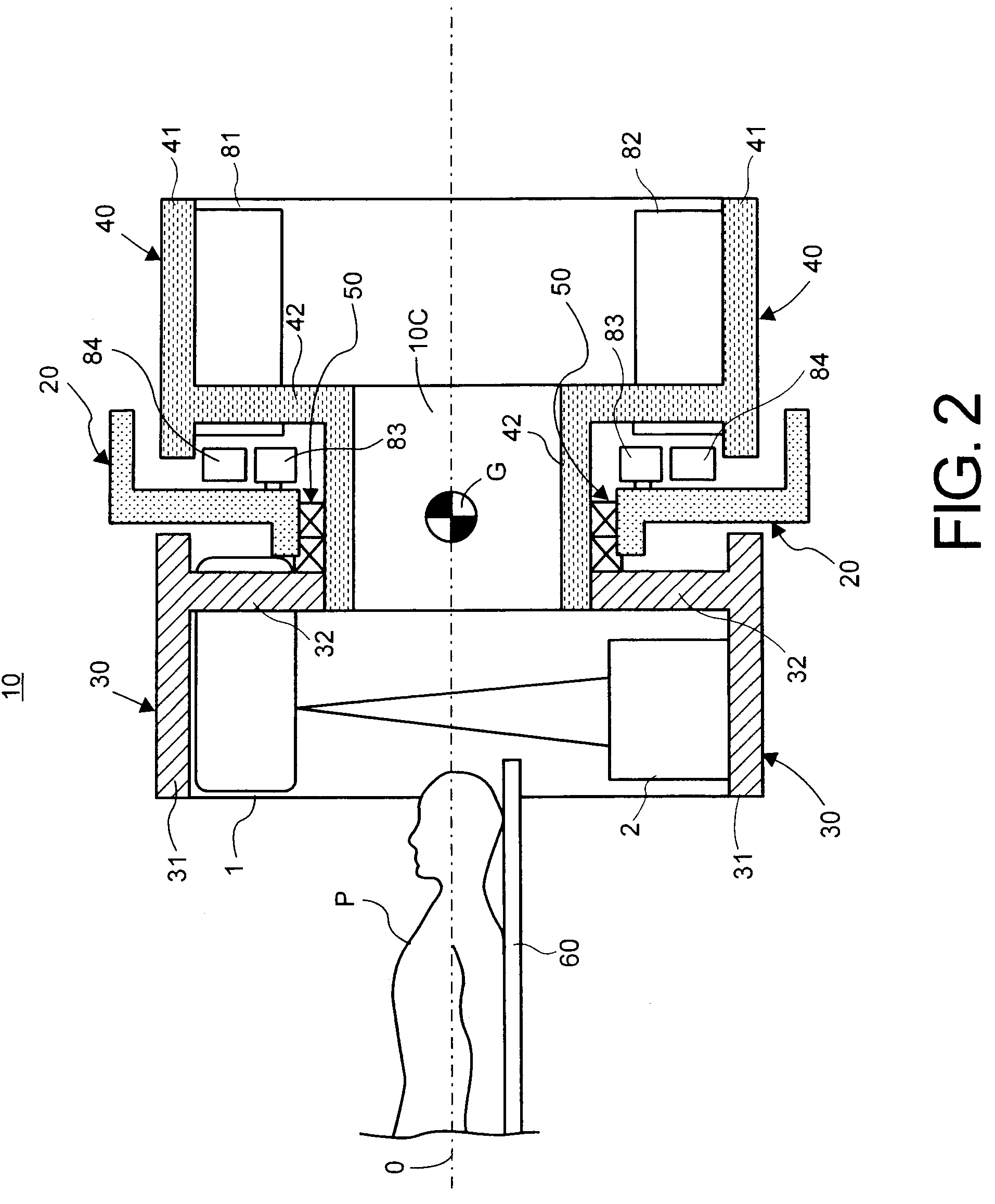
[0034]With reference to the following FIGS. 1-4, embodiments consistent with the present invention will be explained. Usually, a multi-tube type X-ray CT apparatus includes a plurality of X-ray tubes. For better understanding, as an exemplary embodiment of a multi-tube type X-ray CT apparatus consistent with the present invention, a multi-tube type X-ray CT apparatus simply having two X-ray tubes will be explained. Each of two X-ray tubes are to be supplied a high voltage from two high voltage generating units, respectively.

[0035]FIG. 1 shows a block diagram of the construction of the multi-X-ray tube type CT apparatus 100X having a gantry 10 including a rotation frame 30 of a configuration consistent with the present invention. The multi-tube type X-ray CT apparatus 100X includes a bed apparatus (not shown) having a top plate 60 for supporting an object P, a gantry unit 10 including a rotation frame 30 configured to rotate a plurality of X-ray tubes 1A, 1B and a plurality of X-ray ...


PUM

PropertyMeasurementUnit
voltageaaaaaaaaaa
diameteraaaaaaaaaa
angleaaaaaaaaaa

Abstract

An X-ray CT apparatus that achieves a higher quality of reconstructed CT images by preventing displacements of relative positions of the X-ray tube and the X-ray detector from occurring, including a front side rotation frame configured to mount at least one X-ray tube and at least one X-ray detector facing the X-ray tube, and a rear side rotation frame configured to mount rotation units other than the X-ray tube and the X-ray detector in order to access both sides of the gantry.

Description

CROSS-REFERENCE TO RELATED APPLICATIONS[0001]This application claims priority from, and the benefit of, Japanese Patent Application No. 2006-345822, filed on Dec. 22, 2006, the contents of which are expressly incorporated herein by reference in their entirety.BACKGROUND OF THE INVENTION[0002]1. Field of the Invention[0003]The present invention relates to an X-ray computer tomography (CT) apparatus, and more particularly, to a rotation frame configuration in a gantry suitable for a multi-X-ray tube type X-ray CT apparatus.[0004]2. Background of the Invention[0005]In an X-ray CT imaging apparatus having a multi-slice detector, an X-ray source irradiates a fan-shaped X-ray beam through an object and X-ray amounts penetrated through the object are detected by each element of the detector provided opposite the X-ray source. Corresponding detected projection data from the detection are reconstructed in order to display tomography images. A two dimensional multi-slice detector including a ...

Claims


Application Information

Patent Timeline
Patent Type & Authority Patents(United States)
IPC IPC(8): G01N23/00
CPCA61B6/035A61B6/4488
Inventor SADOTOMO, TETSUYANAKANO, MAKOTO
Owner TOSHIBA MEDICAL SYST CORP
Why Eureka
Try Eureka