Page binding apparatus

a page binding machine and spine pressing technology, applied in the direction of typewriters, thin material processing, printing, etc., can solve the problems of time-consuming and labor-intensive processes

Inactive Publication Date: 2005-03-01
SILVERBROOK RES PTY LTD
View PDF21 Cites 29 Cited by
  • Summary
  • Abstract
  • Description
  • Claims
  • Application Information

AI Technical Summary

Problems solved by technology

This is a time consuming an

Method used


Image

  • Page binding apparatus
  • Page binding apparatus
  • Page binding apparatus

Examples


Embodiment Construction

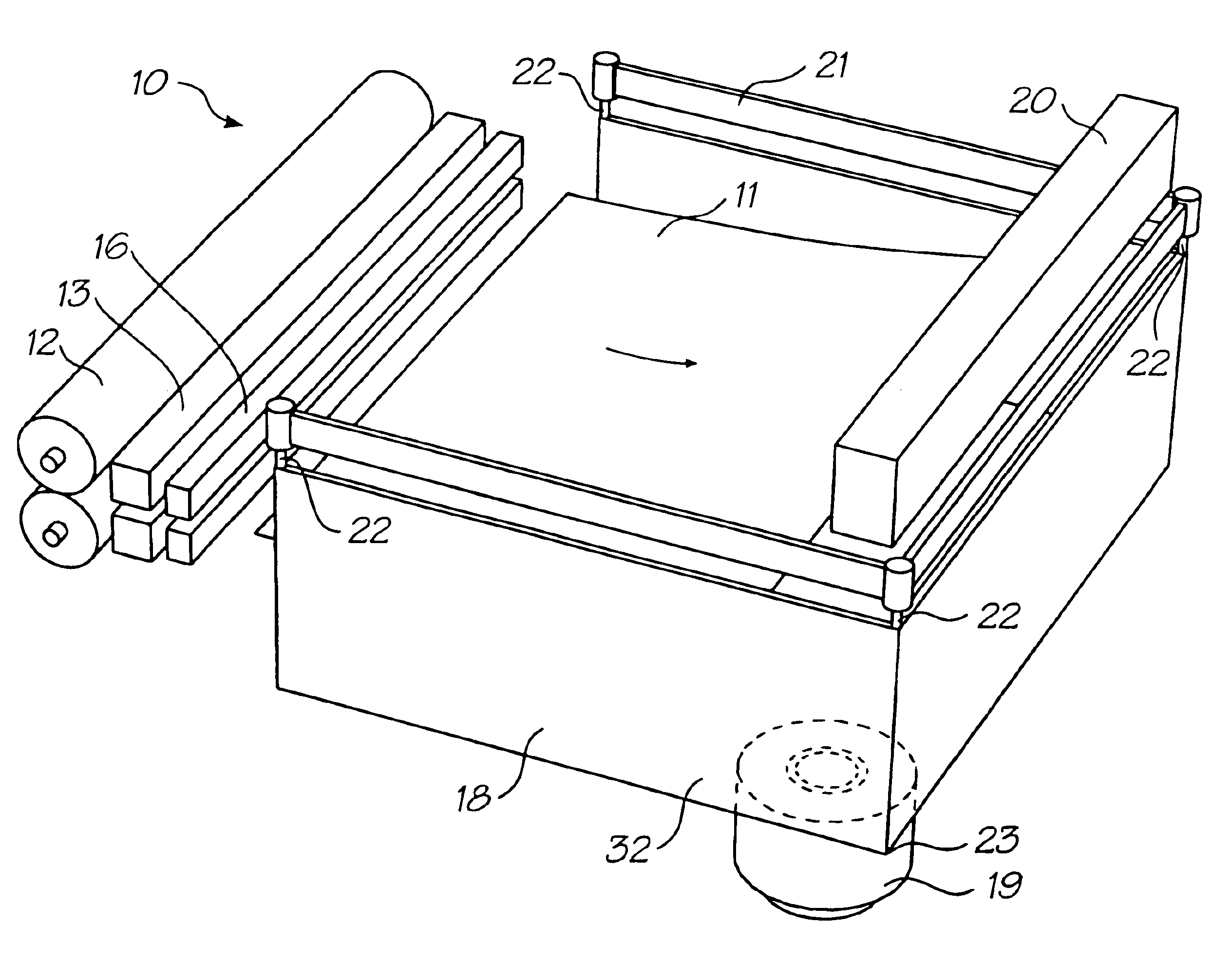
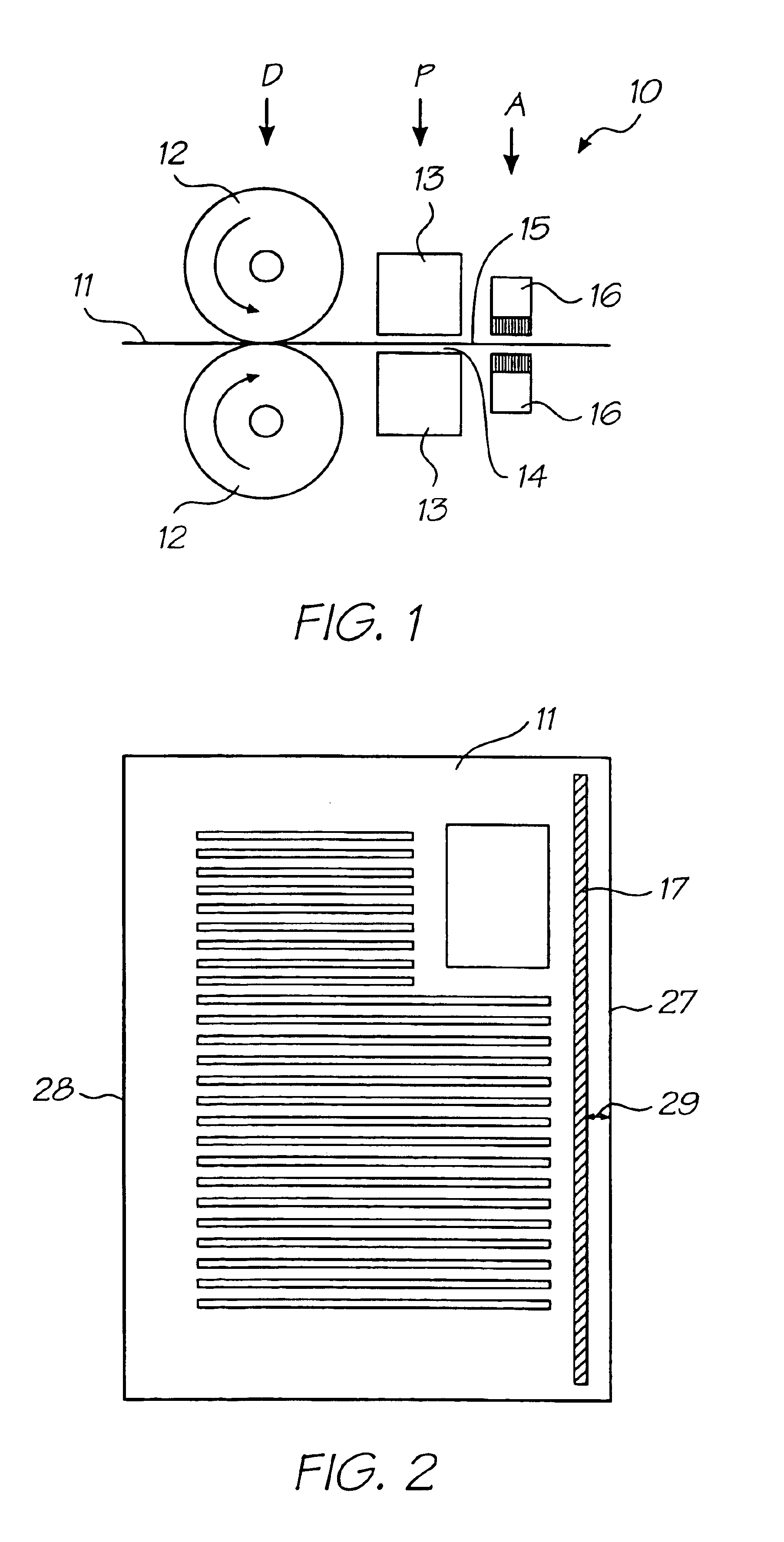
In FIG. 1 of the accompanying drawings there is schematically depicted a path 10 of a page 11 passing through a printer incorporating an adhesive applicator.

Page 11 is driven to the right at a driving station D. Driving station D might comprise a pair of opposed pinch rollers 12 as shown. The page 11 then passes a printing station P and then an adhesive application station A. As an alternative, the adhesive application station A might precede the printing station P, but it is preferred that the adhesive application station follow the printing station so that adhesive on the page 11 does not clog the print head or print heads at printing station P.

For single sided page printing, the printing station P might comprise a single print head 13. The print head 13 might be a pagewidth drop on demand ink jet print head. Alternatively, the print head might be that of a laser printer or other printing device. Where the page 11 is to be printed on both sides, a pair of opposed print heads 13 mi...


PUM


Abstract

The present invention relates to an apparatus for binding pages. The apparatus includes a tray having a support surface for supporting a stack of pages. The support surface is inclined towards a lower-most corner with two side walls being provided which define a corner situated at the lower-most corner of the support surface. A vibrator is coupled to the support surface to induce vibration therein to thereby urge sheets towards the lower-most corner. A binding press is also provided which is operable by moving through a stroke length to bear upon the stack of pages to thereby bind the pages. The support surface is adjustable vertically so as to present the top page of the stack at a preset level to limit the stroke length.

Description

FIELD OF THE INVENTIONThe following invention relates to spine pressing in a page binding machine. More particularly, though not exclusively, the invention relates to pressing an edge portion of a stack of pages where each page has binding adhesive pre-applied to at least one surface adjacent the edge.It is well known to print individual pages of a volume to be bound, then to place all of the printed pages into a stack, to then crop one or more edges of the stack and to then bind the pages together by applying a binding adhesive to an edge of the stack of pages. This is a time consuming and labour-intensive process.It would be more efficient to provide pre-cut, uniformly sized pages, to print one or both surfaces of each page and to provide a strip of binding adhesive to one or both surfaces of each page adjacent the edge to be bound, to accurately place the printed and pre-glued pages in a stack, and to press the pages adjacent the spine so that the adhesive binds the page edges to...

Claims


Application Information

Patent Timeline
IPC IPC(8): B42C9/00
CPCB41J3/44B41J3/60B41J13/106B42C9/0081B65H37/04B42C1/12Y10T156/1798Y10T156/1749B65H39/10
Inventor SILVERBROOK, KIA
Owner SILVERBROOK RES PTY LTD
Why Eureka
Try Eureka