Head protecting airbag device

a technology for protecting airbags and head, which is applied in the direction of pedestrian/occupant safety arrangements, vehicle components, vehicular safety arrangements, etc., can solve the problems of high assembly cost, and large number of working steps, and achieve the effect of quick expansion and inflation of airbags

Inactive Publication Date: 2005-03-01
TOYODA GOSEI CO LTD
View PDF12 Cites 45 Cited by
  • Summary
  • Abstract
  • Description
  • Claims
  • Application Information

AI Technical Summary

Benefits of technology

With this construction, the vertical cell just below the connection port portion has a narrowed opening on the side of the feed passage portion, and the two vertical cells on the two sides thereof are closed at their upper ends. Therefore, the inflating gas flowing from the outlet side portion of the connection port portion into the inflation portion is prevented from flowing in a large quantity into the vertical cells in the vicinity of the connection port portion. In other words, the inflating gas flowing from the outlet side portion into the inflation portion is smoothly guided to the front and rear sides of the feed passage portion. Further, a part of the inflating gas smoothly flows from the vertical cell just below the connection port portion, through a communication passage portion, into the vertical cells at the front and rear ends of the inflation portion. Therefore, the quick expansion and inflation of the airbag are more promoted.

Problems solved by technology

Therefore, in the head protecting airbag device of the prior art, the connecting work becomes complicated in the light of sealing properties, which caused a large number of working steps and a high cost.
As a result, the head protecting airbag device of the prior art needs a large number of working-steps and thus high cost for assembly.

Method used


Image

  • Head protecting airbag device
  • Head protecting airbag device
  • Head protecting airbag device

Examples


first embodiment

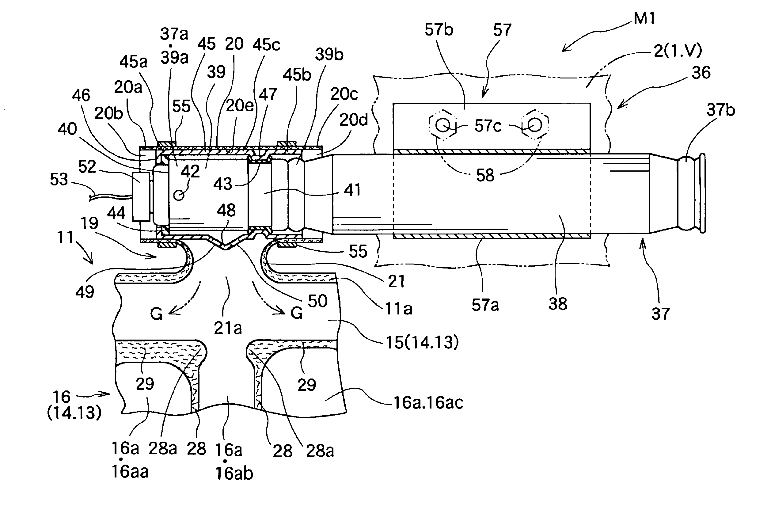
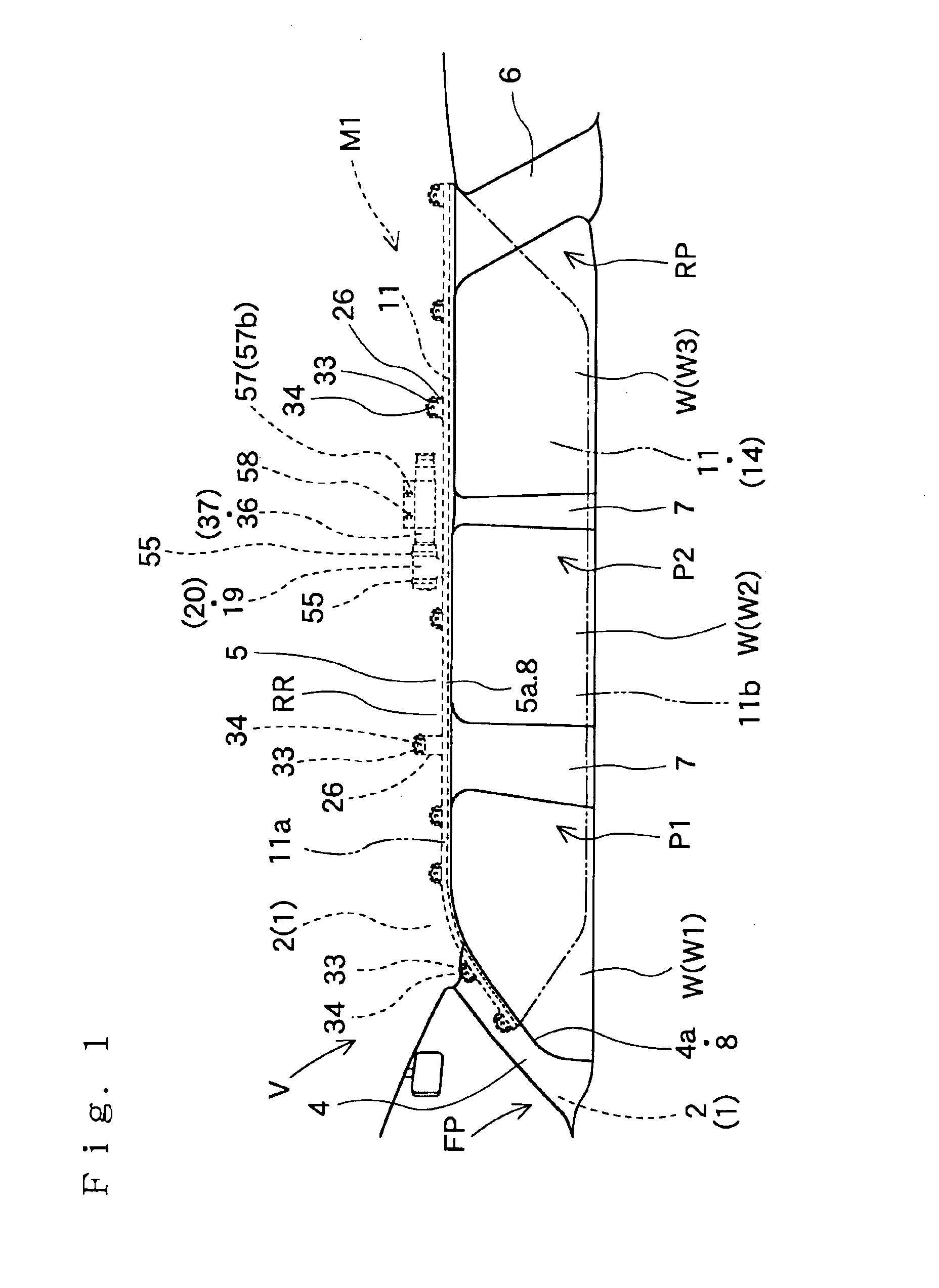
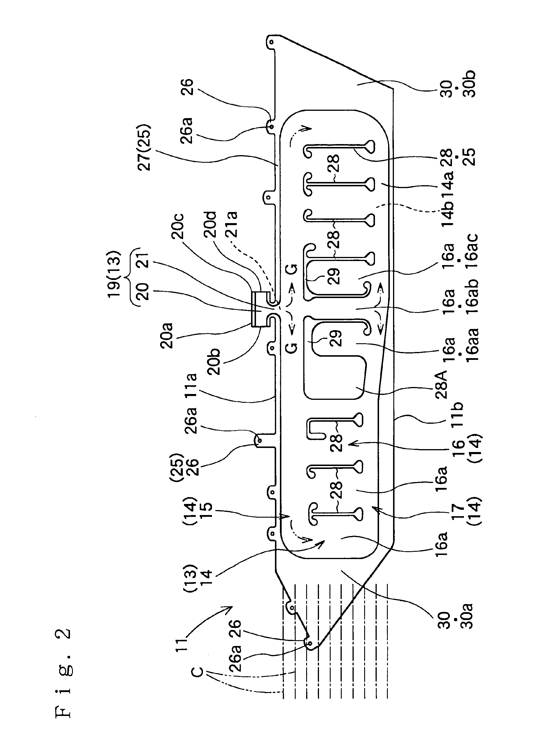
In the airbag device M1 of the first embodiment, on the other hand, the gas outlet ports 49 and 50 of the inflator 36 are opposed to the communication port 21a at the lower end of the connection port portion 19 and arranged toward the side of the feed passage portion 15 of the inflation portion 14. The gas outlet ports 49 and 50 are opened on the outer circumference of the diffuser 45 and are axially directed generally perpendicular to the axial direction of the body portion 37 of the inflator 36 and the diffuser 45 of the inflator 36. Therefore, the communication port 21a in the outlet side portion 21 of the connection port portion 19 is axially directed like the gas outlet ports 49 and 50 generally perpendicular to the axial direction of the inflator 36. In short, the inlet side portion 20 of the connection port portion 19 having the inflator 36 inserted thereinto is arranged in the vehicle V generally perpendicular to the axial direction of the communication port 21a, that is, be...

second embodiment

Moreover, the inflator 66 of the second embodiment includes the body portion 67 and the diffuser 70, as shown in FIGS. 5 and 6. The body portion 67 is formed into a cylinder type having gas discharge ports 68 opened on its outer circumference for discharging the inflating gas G. The diffuser 70 is formed of a metal into a generally cylindrical shape and is assembled with the body portion 67 while covering the gas discharge ports 68, by being pressed on the outer circumference of the body portion 67 at the two ends.

The generally cylindrical body portion 67 is of a stored gas type, which is charged with a cold gas. The body portion 67 has a plurality of gas discharge ports 68 in the outer circumference of the side of a front end 67a, and the connector 52 having the lead wires 53 connected thereto is jointed to the end face of the front end 67a. The diffuser 70 is provided on the side of its leading end (or front end) 70a with a flange portion 71 protruded in the inner circumferential ...

third embodiment

In this third embodiment, the sealed portions on the outer circumference of the inflator 86 on the side of the end portion 80a of the inlet side portion 80 are forced to contact in the circumferential direction with the outer circumference of the diffuser 87. Moreover, the sealed portion of the diffuser 87 is spaced by a clearance S from the outer circumference of the body portion 67. Even if the clamp 55 is fastened with more sealing pressure for sealing the inlet side portion 80 on the diffuser 87 than a predetermined level, therefore, the diffuser 87 is warped to narrow the clearance S in between the body portion 67. As a result, the sealing pressure need not be strictly set, which facilitates the connecting work of the connection port portion 79 and the diffuser 87.

Here, in the second embodiment, as shown in FIG. 6, the clearance S also is formed between the outer circumference of the body portion 67 and the inner circumference of the diffuser 70 at the connection portion by the...


PUM


Abstract

In a head protecting airbag device, an airbag includes an inflation portion and a connection port portion. The connection port portion includes: an outlet side portion having a communication port to the inflation portion at its lower end; and an inlet side portion for inserting an inflator therein. The inflator includes a body portion having a gas discharge port, and a diffuser having a gas outlet port. The diffuser is connected with the body portion so as to cover the gas discharge port, having its two ends forced into contact with the outer circumference of the body portion. The inflator is connected to a connection port portion with good sealing properties and the gas outlet port faces toward the communication port of the connection port portion and thus toward the inflation portion. This head protecting airbag device simplifies the connection structure between the inflator and the airbag while retaining the quick expansion and inflation of the airbag.

Description

This application claims priority from Japanese patent application of Ogata et al, filed Nov. 22, 2001, No. 2001-358093, the complete disclosure of which is hereby incorporated into the present application by this reference.BACKGROUND OF THE INVENTION1. Field of the InventionThe present invention relates to a head protecting airbag device. The airbag of the head protecting airbag device is folded and housed in the upper peripheral edge of a window in the interior side of a vehicle so that it may be expanded and inflated, when it admits an inflating gas, to cover the interior side of the window.2. Description of the Related ArtUsually in the head protecting airbag device of this kind, an inflated airbag protects an occupant. Therefore, the head protecting airbag device is desired, when activated, to develop the airbag quickly. The construction of Unexamined Published Japanese Patent Application No. 2000-296753 is known as the head protecting airbag device which is constructed to expan...

Claims


Application Information

Patent Timeline
Patent Type & Authority Patents(United States)
IPC IPC(8): B60R21/16B60R21/26B60R21/20B60R21/213B60R21/214B60R21/233B60R21/262
CPCB60R21/232B60R21/261B60R21/26B60R2021/23316
Inventor OGATA, TETSUYANAKAMURA, EISHICHITANASE, TOSHINORI
Owner TOYODA GOSEI CO LTD
Why Eureka
Try Eureka