Illuminated keyboard switch structure

Inactive Publication Date: 2005-03-01
DARFON ELECTRONICS CORP
View PDF16 Cites 163 Cited by
  • Summary
  • Abstract
  • Description
  • Claims
  • Application Information

AI Technical Summary

Problems solved by technology

As a result, manufacture of the conventional illuminated keyboard is complicated, a

Method used


Image

  • Illuminated keyboard switch structure
  • Illuminated keyboard switch structure
  • Illuminated keyboard switch structure

Examples


Embodiment Construction

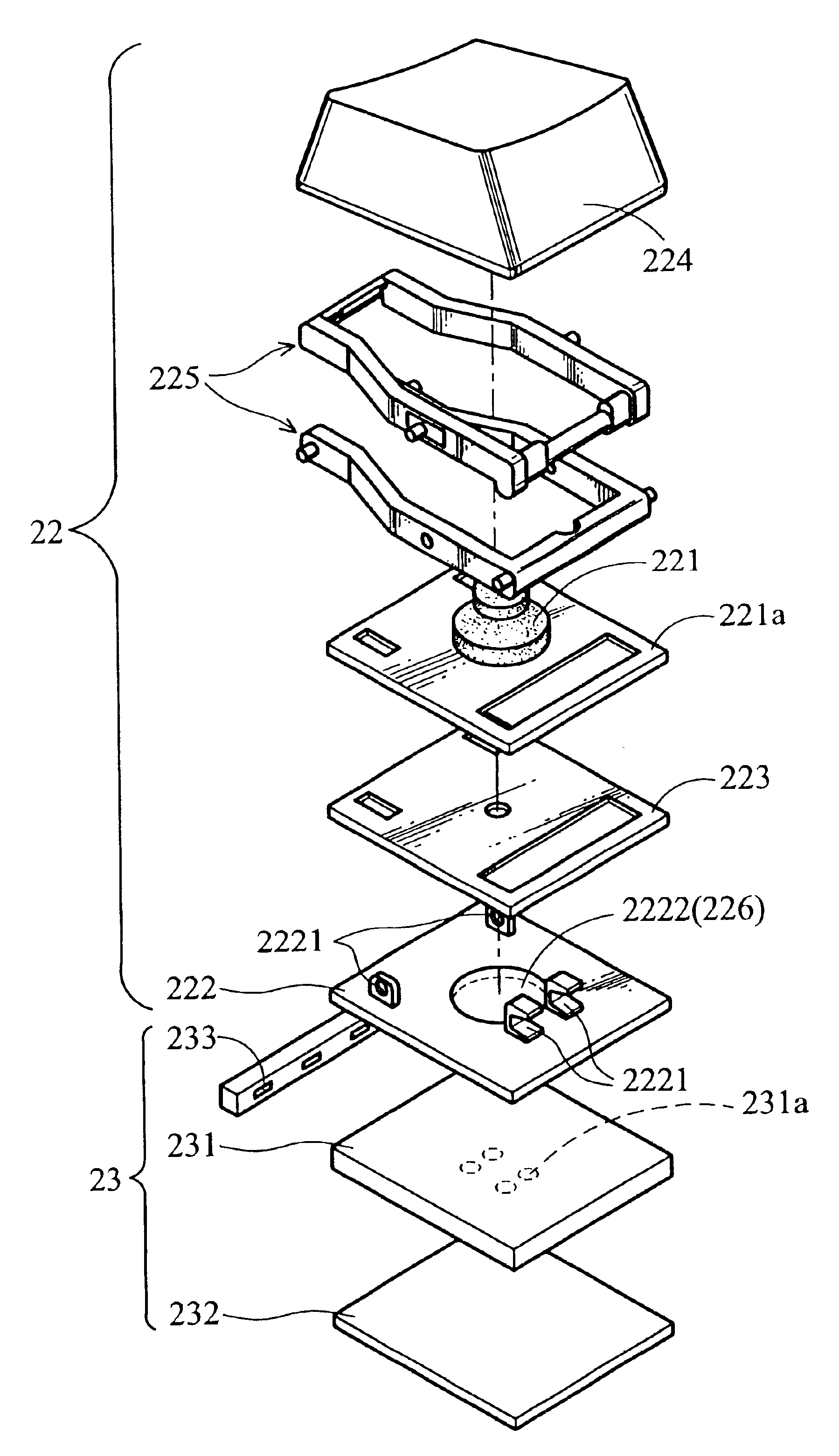
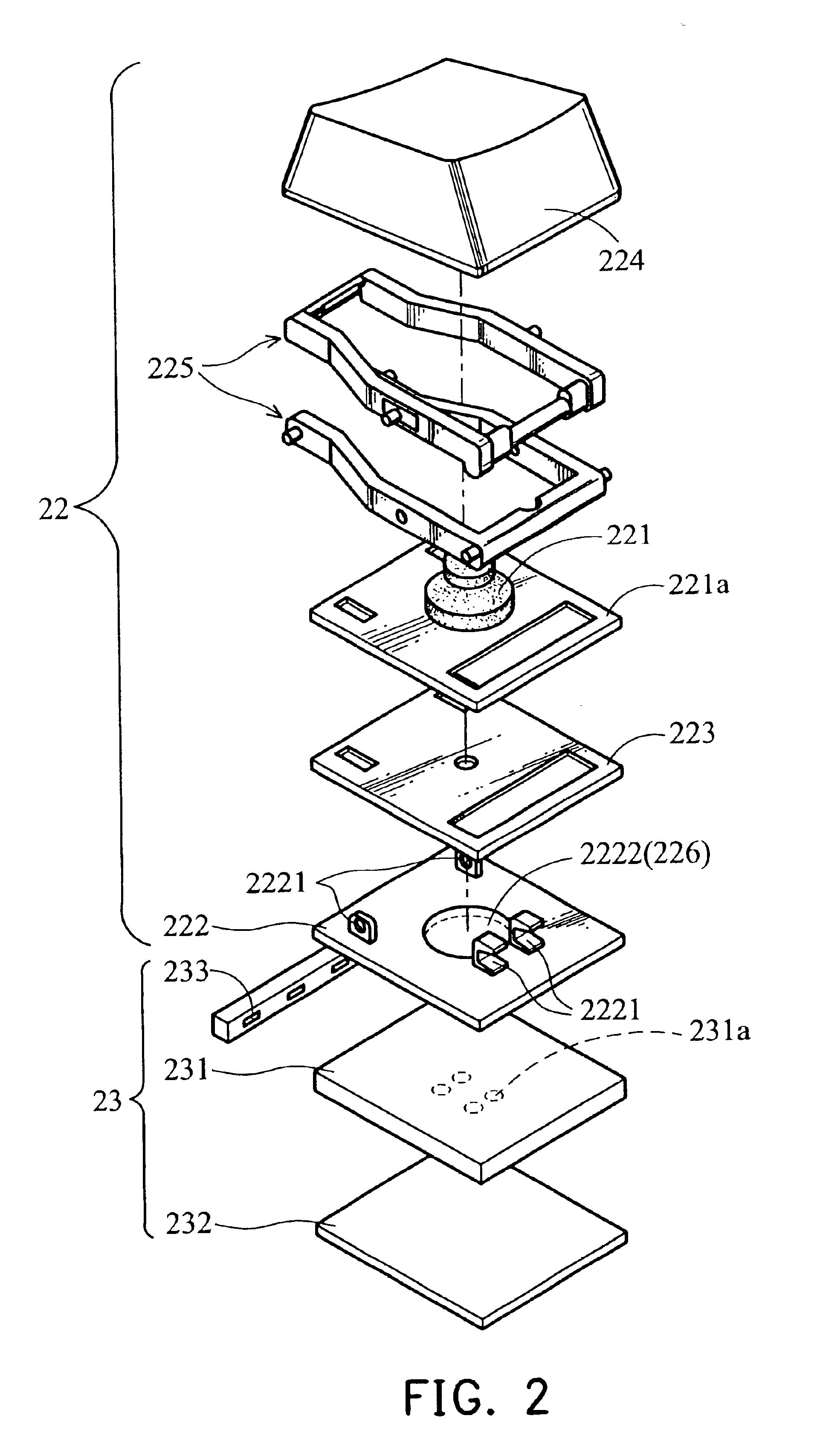
FIG. 2 is a schematic view of an illuminated keyboard 20 as disclosed in this invention. As shown in FIG. 2, the illuminated keyboard 20 comprises a key portion 22 and a backlight device 23. It is noted that the illuminated keyboard 20 further comprises a housing, a cover, and other elements of a conventional keyboard. However, for simplicity, such elements are omitted.

The key portion 22 is disposed on the housing (not shown) of the illuminated keyboard 20, and comprise a seat 222, a membrane circuit board 223, a cap 224, an elastic member 221, and a connecting assembly 225. Referring to FIG. 3, the seat 222 is provided with a plurality of fixed members 2221. One end of the connecting assembly 225 is connected to fixed members 2221 of the seat 222 in a slideable and rotatable manner, and the other end of the connecting assembly 225 is connected to the cap 224. Thus, the cap 224 can move upward and downward relative to the seat 222. The elastic member 221 is disposed between the memb...


PUM


Abstract

An illuminated keyboard having a key portion, a backlight device, a light-condensing plate, a diffuser, a printed circuit board, and a light source. The key portion includes a seat and a key, and the key is disposed on the seat in a manner such that it is moved upwardly and downwardly. The backlight device is disposed beneath the key portion to illuminate the key portion. The light-condensing plate is disposed between the light guide and the key portion. The diffuser is disposed between the light guide and the key portion. The printed circuit board is disposed between the seat and the backlight device. The light source is disposed on the printed circuit board.

Description

BACKGROUND OF THE INVENTION1. Field of the InventionThe invention relates to an illuminated keyboard; in particular, an illuminated keyboard with improved illumination capability.2. Description of the Related ArtSince computers may be used in various environments, such as dark environments, an illuminated keyboard has been provided.FIG. 1 is a schematic view of a conventional illuminated keyboard 10 as disclosed in U.S. Pat. No. 6,284,988. The illuminated keyboard 10 comprises a key switch 11, and a backlight device 15 disposed in the key switch 11. Specifically, the key switch 11 comprises a seat 111, a printed circuit board 112, an elastic member 113a, a cap 114, and a connecting assembly 115. The printed circuit board 112 is disposed on the seat 111. The elastic member 113a is formed on the printed circuit board 112. The cap 114 corresponds to the elastic member 113a. One end of the connecting assembly 115 is connected to fixed members 111a of the seat 111 in a slideable and rota...

Claims


Application Information

Patent Timeline
IPC IPC(8): F21V8/00H01H3/12
CPCG02B6/0005G02B6/0068G02B6/0081H01H3/125H01H2219/018H01H2219/044H01H2219/056H01H2219/06H01H2219/062H01H2219/0621
Inventor CHIANG, CHIH-HSIANGYEH, LIANG-TA
Owner DARFON ELECTRONICS CORP
Why Eureka
Try Eureka