Lead retention bushing

a technology of retention bushing and lead, which is applied in the direction of electrical apparatus, connection, coupling device connection, etc., can solve the problems of excessive pinching of conductors, inconvenient assembly, and insufficient clamping of the cord, so as to relieve the strain on the cord connection, facilitate assembly, and limit movement

Inactive Publication Date: 2005-03-01
THOMAS IND INC
View PDF5 Cites 0 Cited by
  • Summary
  • Abstract
  • Description
  • Claims
  • Application Information

AI Technical Summary

Benefits of technology

Again, the bushing preferably has a pair of deflectable, angled snap tabs in which case the housing would be formed with a pair of opposed notches opening to the inside of the housing slot. The system can further include a drive motor mounted to the housing at the open face to apply a retaining force against the trailing end of the bushing which forces the tabs of the bushing to deflect against a side of the notches and thus limit movement (such as vibration and rattling) of the bushing with respect to the housing.
The invention thus provides a low-cost bushing that can act as a strain relief bushing or an open-closed bushing. The bushing can be easily assembled to a device to protect non-corded leads and / or to relieve strain on the cord connection by applying a clamping force to the cord sheathing without damaging the conductors. The clamping force is sufficient to withstand substantial pulling force (preferably at least 35 pounds). With the snap tabs engaged in the notches and the motor assembled to the housing, the bushing is prevented from rattling and the necessary clamping force is maintained. Removal of the bushing without tools is also prevented. Further, the shape and size of the slots can be configured to accommodate a variety of lead or cord diameters with a single bushing.

Problems solved by technology

If the opening is too large, the bushing will not properly clamp the cord.
If it is too small, it may pinch the conductors excessively.
The need for numerous bushings for the various chord diameters can incur costly inventory and production expenses.

Method used


Image

  • Lead retention bushing
  • Lead retention bushing
  • Lead retention bushing

Examples


Embodiment Construction

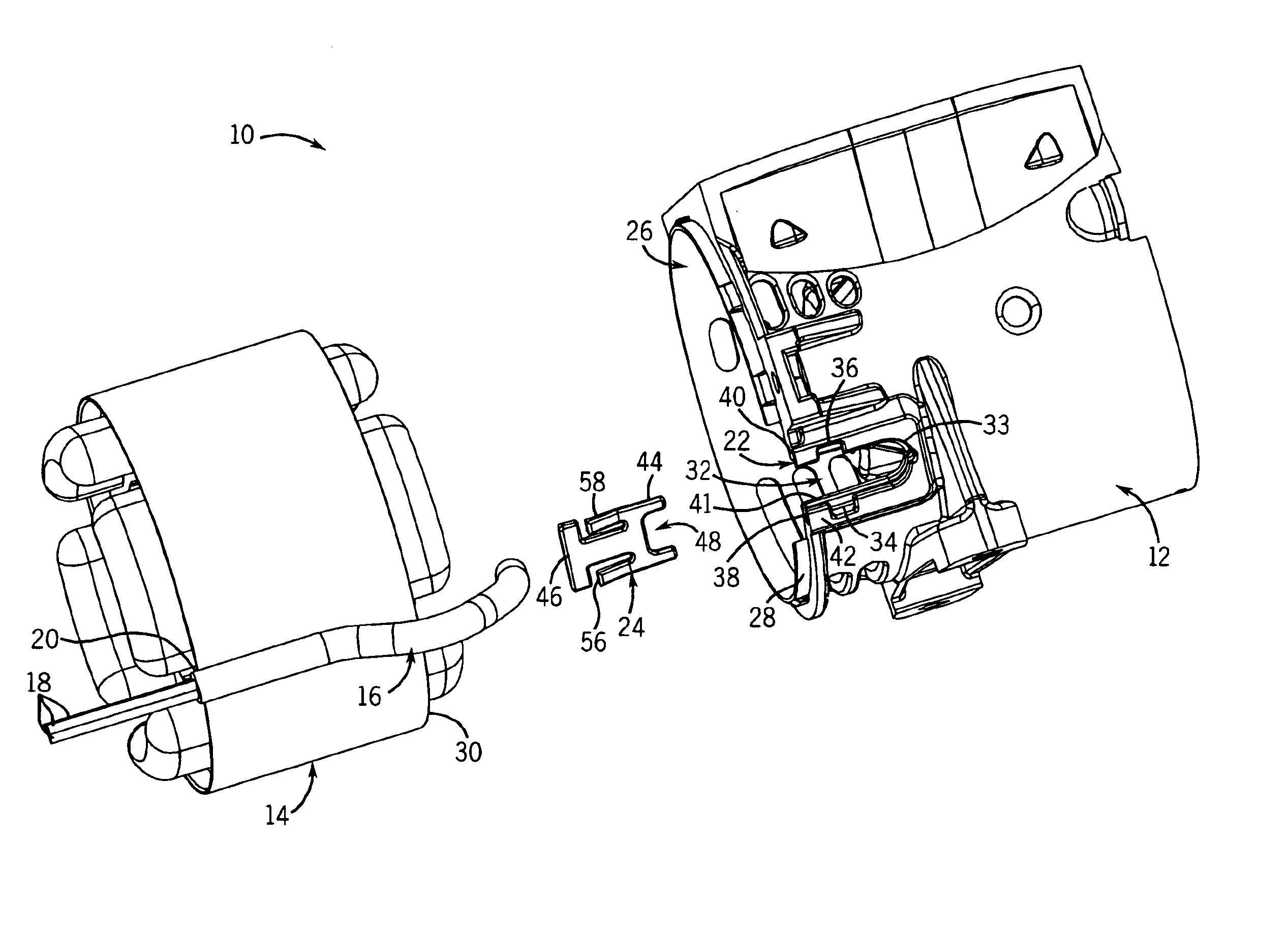
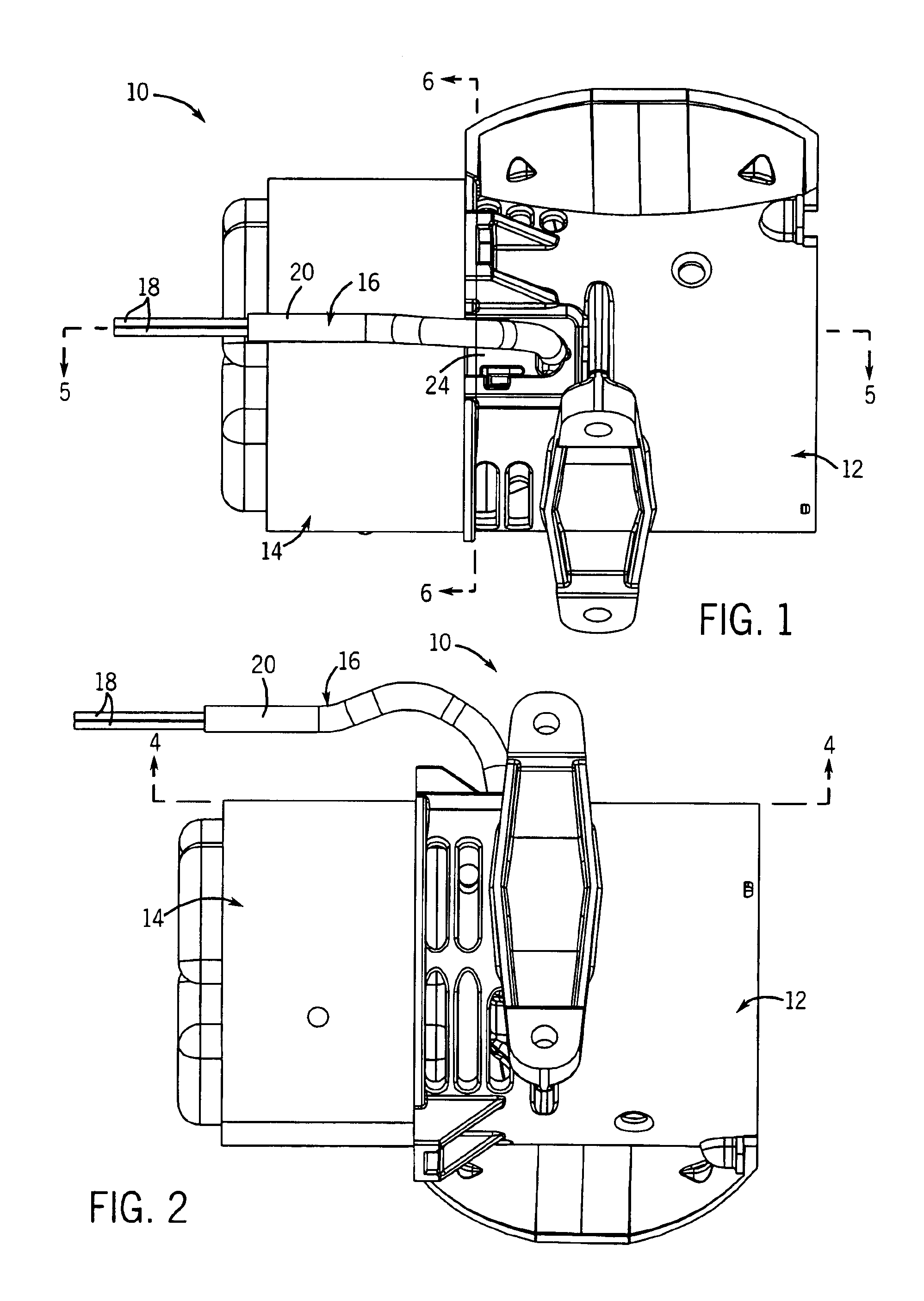
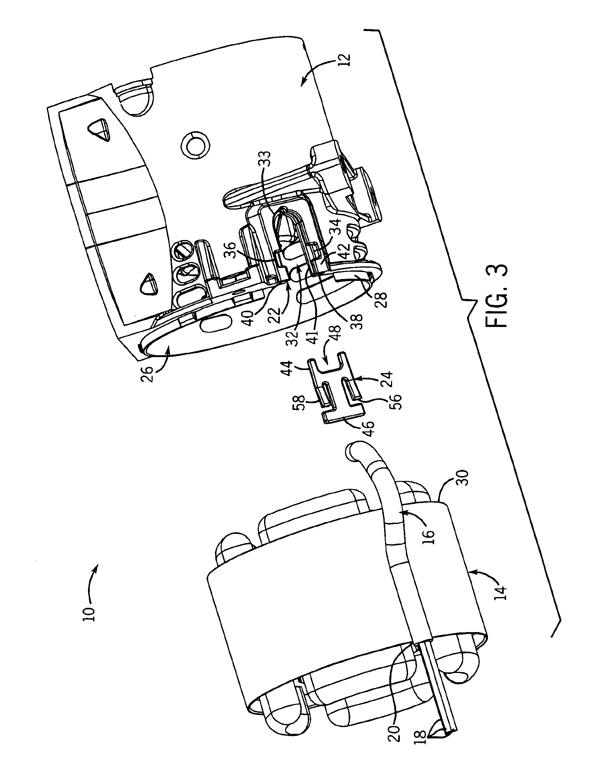
Referring to FIGS. 1-3, the present invention provides a power cord retention system with a lead retention bushing. The bushing can be characterized as either a “strain relief bushing”, such as shown in FIG. 7A, for clamping against a power cord or as an “open-closed bushing” (or “lead-edge protector”), such as shown in FIG. 7B for protecting the lead edge of individual conductive leads (not part of a cord arrangement).

In either case, the bushing is particularly suited for use with a compressor / pump 10 having associated piston / cylinder assemblies (not shown) contained in a crankcase housing 12 to which is mounted an AC drive motor 14. The motor 14 has a either a power cord 16 with three conductor leads 18 contained in its insulating sheathing 20 (or separate conductor leads not contained in a cord sheathing).

The housing 12 is preferably generally cylindrical and made of a suitable plastic. The wall of the housing 12 is formed with a pocket 22 for receiving a bushing 24, as described...


PUM


Abstract

A conductor lead and power cord retention system for a compressor/pump has a unique bushing for capturing and pinching the cord in an opening in the pump housing. The bushing has a leading end defining an open-ended slot. The bushing slides into a pocket in the housing and overlaps an open-ended slot in the housing. Overlapping the slots creates a bounded (circular for example) opening sized to snuggly pinch the cord sheathing without damaging the conductors. The slots are shaped and sized to accommodate a variety of cord diameters. The bushing is retained in the recess by a pair of angled snap tabs that engage notches and further by mounting of the drive motor to the housing, which forces the bushing against the housing to prevent rattling as well as helps maintain the necessary pinch force and prevents the bushing from being removed without tools.

Description

CROSS-REFERENCE TO RELATED APPLICATIONSNot applicable.STATEMENT OF FEDERALLY SPONSORED RESEARCH OR DEVELOPMENTNot applicable.BACKGROUND OF THE INVENTIONThe present invention relates to relieving pull strain on electric power cords, and in particular to a special strain relief bushing design.Strain relief bushings and open-closed bushings are commonly used at the connection of power cords and electrical leads to the body of an electrical device. Such bushings mount into openings in the housings of the devices to protect the conductor leads and can clamp the sheathing or insulation surrounding the conductor leads so that if the cord is pulled on the leads are not torn loose from the motor. Protecting the leads and relieving the strain on the leads reduces the chance that the electrical connection will be disrupted.These bushings must perform sufficiently to satisfy national agency standards (such as United Laboratories), for example, regarding being irremovable from the device without...

Claims


Application Information

Patent Timeline
Patent Type & Authority Patents(United States)
IPC IPC(8): H01R13/58H01R13/502H01R13/508
CPCH01R13/5837H01R13/508
Inventor WEISS, PAUL J.
Owner THOMAS IND INC
Why Eureka
Try Eureka