Method and apparatus for separating liquid from a multi-phase liquid/gas stream

a multi-phase liquid and gas stream technology, applied in the direction of liquid degasification, separation process, borehole/well accessories, etc., can solve the problems of pump replacement, expensive and time-consuming operation, and production shut down

Inactive Publication Date: 2005-03-01
COOPER CAMERON CORP
View PDF13 Cites 48 Cited by
  • Summary
  • Abstract
  • Description
  • Claims
  • Application Information

AI Technical Summary

Problems solved by technology

However, one of the problems with this conventional solution is that of pump replacement.
This involves removal of the tubing strings and is an expensive and time-consuming operation which shuts down production for a significant matter of time.
A further problem arises in controlling the pump 17.

Method used


Image

  • Method and apparatus for separating liquid from a multi-phase liquid/gas stream
  • Method and apparatus for separating liquid from a multi-phase liquid/gas stream
  • Method and apparatus for separating liquid from a multi-phase liquid/gas stream

Examples


Embodiment Construction

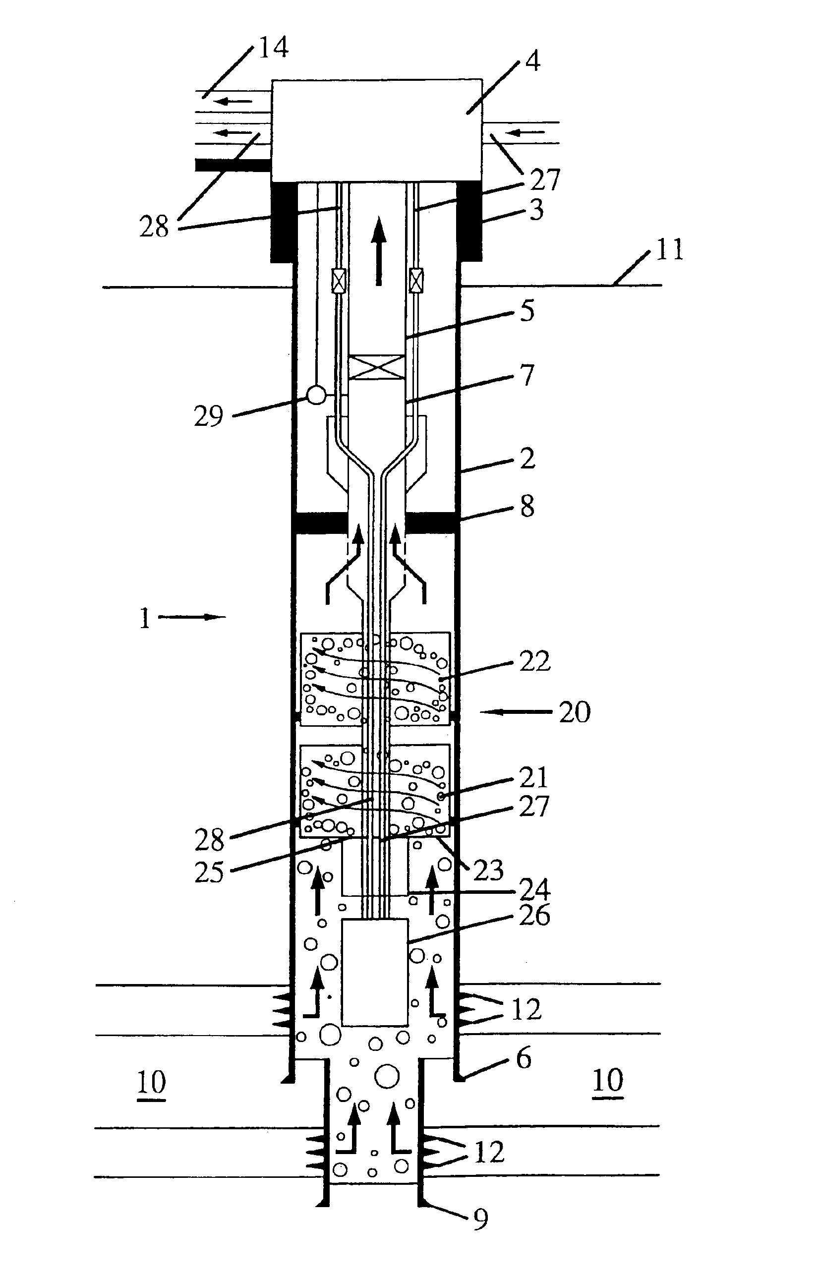
The concept of the present invention is illustrated in FIG. 3. A tubular separation unit 20 includes one or more (two as shown) centrifugal flow-induced liquid separator or separators 21, 22 with a lower inlet 23 for the multi-phase liquid / gas stream flowing in above the shoes 6, 9 through the perforations 12, at the bottom of the casing 2 and casing liner above shoe 9. Liquid and gas are separated in the centrifugal separators 21, 22 and liquid separated from the gas passes through a transfer conduit or sleeve 24 from an outlet 25 into a pump 26, which is a gas injection pump, and, under the pressure of gas fed to the pump from a gas operation line 27, liquid is removed through a liquid outlet line 28.

Separated gas is allowed to flow into the production tubing 5 and up to tree 4 inside the casing 2. Well pressure and temperature monitors 29 are provided as conventional.

The lower end of the well 1 is illustrated in somewhat more detail in FIG. 4 which, in particular, shows detail of...


PUM

PropertyMeasurementUnit
pressureaaaaaaaaaa
velocityaaaaaaaaaa
diameteraaaaaaaaaa

Abstract

A tubular separation unit insertable into a caisson or tube for separating liquid from an upward flowing liquid / gas multi-phase stream, and including a centrifugal flow-induced liquid separator having a multi-phase gas / liquid inlet, a liquid outlet, and a gas stream outlet; a liquid transfer conduit connected to the liquid outlet of the flow separator; and a pump for pumping liquid, disposed below the separator and including a pump liquid inlet connected to the liquid transfer conduit and through which liquid separated in the separator is received, and a pumped liquid outlet through which separated liquid is, in use, caused to flow selectively.

Description

BACKGROUND OF THE INVENTION1. Field of the InventionThe present invention relates to a method and apparatus insertable into a tubular pressure containing pipe (such as in an oil well), caisson, silo riser or conductor for separating liquid from an upward flowing liquid / gas multi-phase stream. More particularly, the method and apparatus are capable of providing a solution to the problem of eliminating and removing liquids from a multi-phase well or riser system where the build up of liquids can cause a significant loss of production.FIG. 1 is a example schematic illustration of a typical hydrocarbon well completion. The well is not shown to scale. A multi-phase producing well such as illustrated in FIG. 1 may have its wellhead located on the sea-bed or on a platform or on land. For simplicity the invention described has the wellhead shown on the surface.A well 1 has a production casing 2 at the top of which is secured a wellhead 3 and a tree 4. A production tubing string 5 is suspend...

Claims


Application Information

Patent Timeline
Patent Type & Authority Patents(United States)
IPC IPC(8): E21B43/34E21B43/12E21B43/38B01D17/038
CPCE21B43/38E21B43/121E21B43/385
Inventor HOPPER, HANS P.
Owner COOPER CAMERON CORP
Why Eureka
Try Eureka